-37-
GENERAL INFORMATION
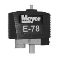
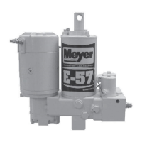
Using the proper guidelines and precautions, the E-
58H, E-78 & E-88 units are easy to disassemble and
reassemble. Figure 3-1 (page 38) is an exploded view
which applies to the E-88. Figure 3-2is an exploded
view which applies to the E-58H & E-78. It should be
used as the primary reference for proper reassembly.
Where necessary, this section includes additional
information, photographs and illustrations to assure
proper and efficient repairs.
UNIT DISASSEMBLY AND REASSEMBLY
Many repair procedures, including removal and
replacement of the “A”, “B”, “C”, “D” and “E” Solenoid
Valves, can be accomplished without removing the
unit from the vehicle. While Figures 3-3 through 3-120
show the unit clamped in a vise, make all possible
repairs on the vehicle when possible.
NOTE: Pump Assembly should not be disassembled
since it cannot be serviced with the exception of the
pressure relief valve (pages 43) and pump shaft seal
which is covered separately in this section.
Disassembly
See Figures 3-3 through 3-31 (pages 40-59).
Reassembly
See Figures 3-32 through 3-120 (pages 59-69) for
important reassembly points.
See Figures 3-91 through 3-110 (Pages 62-66) for
Crossover Relief reassembly.
Additional Reassembly Points
O-Rings- Coat liberally with hydraulic fluid and
position carefully to minimize possibility
of damage during assembly.
Fasteners- Torque all fasteners which are specified
to insure proper reliability and prevent
damage due to over-tightening.
PUMP
Shaft Seal Replacement
NOTE: Do not disassemble pump assembly.
1. Remove motor as shown in Figures 3-13 and
3-14 (page 42).
2. Using an appropriate tool, pry out the original
shaft seal, being careful not to damage the shaft
or pump housing.
3. Liberally coat the replacement seal I.D. with
hydraulic fluid and apply a very light film of
Permatex Form-A-Gasket No. 2 or equivalent to
the replacement seal O.D.
4. C a r e f u l l y s l i d e t h e r e p l a c e m e n t s e a l
(metal side up) over the shaft until it is squarely
against the pump housing.
5. Center a 11/16” hex deep socket over the seal and
use it and a plastic or leather mallet to squarely
drive the seal into the pump.
6. Replace the motor as shown in Figures
3-88 & 3-89 (page 61).