ELECTRO LIFT
®
UNIT COMPONENTS
MOTORS ( 3”) E-46, E-46H and E-47, E-47H
The 12-volt DC high torque motor used on the Electro
Lift
®
units are interchangeable among all four models.
Its function in all four applications is to drive the
hydraulic pump. The motor is only energized and
operating when pressurized hydraulic fluid is required.
Two different brand motors were used. While they are
interchangeable and have nearly identical performance
characteristics, they have distinctive design differences.
American Bosch
The American Bosch motor is a four pole, permanent
magnet motor which consists primarily of a 3" diameter
solid steel frame, armature, brushes and ceramic
permanent magnet fields. Because the fields are
permanent magnets, they do not require electrical
current to operate. Therefore, the motor requires lower
amperage to produce a given amount of power.
Electro Lift
®
units equipped with an American Bosch
motor cannot be used on vehicles with a positive
ground electrical system since the motor will rotate
backwards. Positive ground vehicles will require
modification of the brush assembly.
Prestolite - (obsolete)
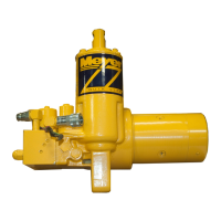
MOTOR (4-1/2”) E-57, E-57H
Iskra - Single and Two terminal
The Iskra motor is a four pole, electromagnet motor
which consists primarily of a 4-1/2" diameter solid steel
frame, armature, brushes, field coils and pole pieces.
This motor can be used on vehicles with either the
common negative ground electrical system or the
positive ground electrical system.
HYDRAULIC PUMP
The pump in a hydraulic system employs an external
source of power to apply a force to a liquid. A pump
develops no power of its own. It simply transfers power
from an external source (the electric motor on the
Electro Lift
®
unit) to the liquid in the hydraulic system.
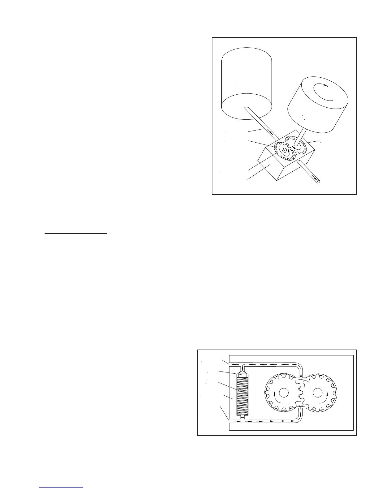
The basic operating principles of the hydraulic pump
used in the Electro Lift
®
units are quite simple. Figure
1-7 illustrates the basic components of a positive
displacement gear type pump and their functions. The
pumping action takes place within the pump chamber
which is connected to the reservoir by the intake line.
The pump chamber has an outlet line in which the liquid
under motion and pressure leaves the pump to perform
work.
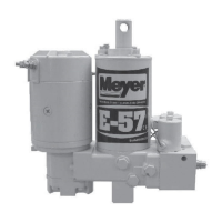
PRESSURE RELIEF VALVE
A basic pressure relief valve is shown in
Figure 1-8. It consists of a poppet valve and a valve
spring. Both are located in a passage which connects
the inlet passage to the outlet passage. The poppet
valve is normally held closed by the valve spring,
sealing the connecting passage from the pressurized
outlet passage. The poppet valve, being a piston, is
exposed to the pressurized hydraulic fluid in the outlet
passage. Whenever the hydraulic pressure against the
poppet valve becomes greater than the pressure being
exerted on the poppet valve from the opposite
direction by the valve spring, the poppet valve will
open. This allows some of the pressurized hydraulic
fluid to flow through the connecting passage to the
non pressurized inlet passage. The effect is to lower
the pressure in the outlet passage which will allow the
valve spring to close the poppet valve again.
FIGURE 1-7
ELECTRO LIFT® UNIT COMPONENTS
RESERVOIR
ELECTRIC
MOTOR
F
L
O
W
OUTLET LINE
INTAKE LINE
PUMP CHAMBER
PUMP HOUSING
DRIVE GEAR
DRIVEN GEAR
F
L
O
W
OUTLET PORT
POPPET
VALVE
VALVE
SPRING
PUMP HOUSING
INLET PORT
FIGURE 1-8
-19-