Under a condition, such as when a hydraulic cylinder
is extended to the end of its stroke, eliminating
additional space for the pressurized hydraulic oil to
be pumped into, the alternate opening and closing of
the poppet valve controls the pump’s pressure output
and provides an escape for the pressurized hydraulic
fluid.
The pressure relief valve used in the Electro Lift
®
pump,
while more sophisticated than the one described,
functions in the same manner. The pump pressure relief
valve may be adjusted on the E-46 & E-47 models to
the specified pressure of 1650 P.S.I. by adjusting the
set screw after installing a suitable pressure gauge of
2500 P.S.I. in the circuit. Note: The E-57 Model has a
nonadjustable pressure relief valve and is factory set
to 2000 P.S.I.
SOLENOID VALVES
Hydraulic valves are simple in concept and all have
the same basic function: Control the direction of oil
flow. One type of Solenoid Valve is used on the models
E-46 and E-46H and three types are used on models
that Power Angle.
Each Solenoid Valve consists of two components: the
Cartridge and the Coil.
Cartridge
The Cartridge consists of the hydraulic valve
mechanism and an armature which enables the
valve mechanism to be operated and controlled
electrically. The Cartridge is designed to screw in
and out of the Electro Lift
®
units much like the
typical “spark plug”.
Coil
The Coil is the electrical component which operates
the Cartridge’s valve mechanism by producing
magnetism which pulls the Cartridge’s armature
toward it. Since the armature is connected to the
valve mechanism’s only moving part, it is pulled
by the armature.
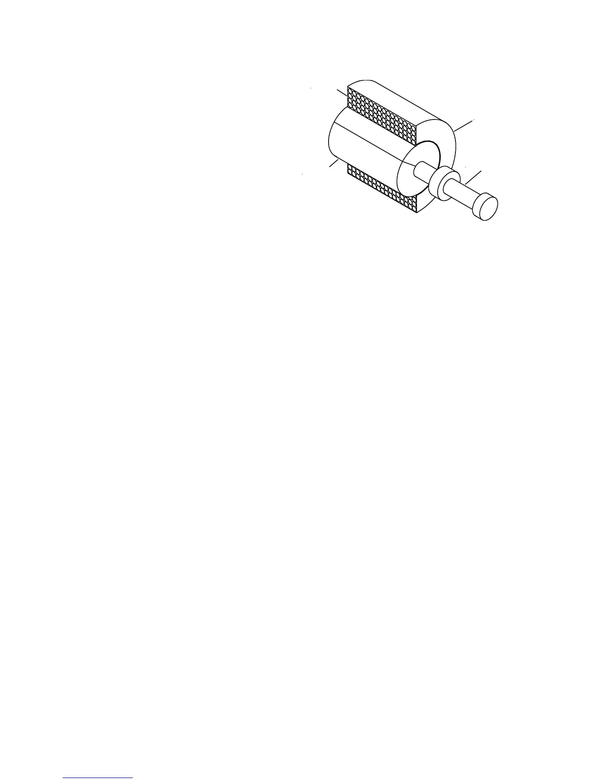
Figure 1-9 illustrates the typical Coil. Whenever
electrical current flows to the Coil, it flows through
the winding, which consists of numerous turns of
copper wire. The flow of current through the
winding produces a magnetic field which pulls the
soft iron armature further into the Coil.
The armature pulls the valve spool or poppet valve
into its alternate (energized) position. Not illustrated
is an integral coil spring, which is compressed
when the armature is pulled by the magnetism.
When the current flow ceases, the magnetic field
disappears and the compressed coil spring pushes
the armature back to its original (de-energized)
position.
FIGURE 1-9
COIL
VALVE SPOOL
WINDING
ARMATURE
“A” Solenoid Valve
The “A” Solenoid Valve is used in all Models. The “A”
Cartridge contains a poppet valve whose static or
de-energized position is closed. Its energized position
is open.
On all four models, the “A” Solenoid Valve retains
hydraulic fluid in the lift cylinder. It is energized
(opened) to allow the hydraulic fluid to flow from the
lift cylinder back to the reservoir, enabling the plow to
lower by gravity.
The “A” Solenoid Valve is designed to remain energized
(open) while the plow is lowered, plowing snow. This
is the “float” feature which insures that the plow
maintains contact with the ground contour.
“B” Solenoid Valve
The “B” Solenoid Valve is used on the Power Angle
Electro Lift
®
models. The “B” Cartridge contains a
spool valve whose static (de-energized) position allows
the pressurized hydraulic fluid to flow to the
“C” Solenoid Valve. In the energized position, the
pressurized hydraulic fluid is diverted to the lift cylinder,
raising the plow.
“C” Solenoid Valve
The “C” Solenoid valve is used on the Power Angle
Electro Lift
®
models. The “C” Cartridge contains a
spool valve whose static (de-energized) position allows
the pressurized hydraulic fluid to flow to the right power
angling cylinder which angles the plow to the left. At
the same time, it allows the hydraulic fluid being forced
from the retracting left power angling cylinder to flow
through the “C” Cartridge back to the reservoir.
In the energized position, the pressurized hydraulic
fluid is diverted to the left power angling cylinder,
angling the plow to the right. Also, the hydraulic fluid
being forced from the retracting right power angling
cylinder flows through the “C” Cartridge back to the
reservoir.
-20-
ELECTRO LIFT® UNIT COMPONENTS CONT.