DIAGNOSTIC FLOW CHART FOR
E-46, E-47 and E-57 ELECTRO LIFT
®
UNITS
These charts are intended to be used as an aid in diagnosing problems on the Electro Lift
®
units. They are not a substitute for factory
training and experience. Be certain to read the General Information and Testing Tips sections before attempting any troubleshooting.
IMPORTANT: Maintenance and repairs must be performed with the moldboard on the ground.
General Information
Before any troubleshooting is started, make certain the following conditions are met.
1. The moldboard is pointing straight ahead. This can often be done by coupling the left cylinder into the right cylinder and
pushing the moldboard by hand.
2. The power angling cylinders must be installed correctly on to the A- frame. The left cylinder (Driver’s side) has a hose
attached with a male half of a coupler at the end; the right cylinder (Passenger side) has a hose attached with a female half
of a coupler at the end.
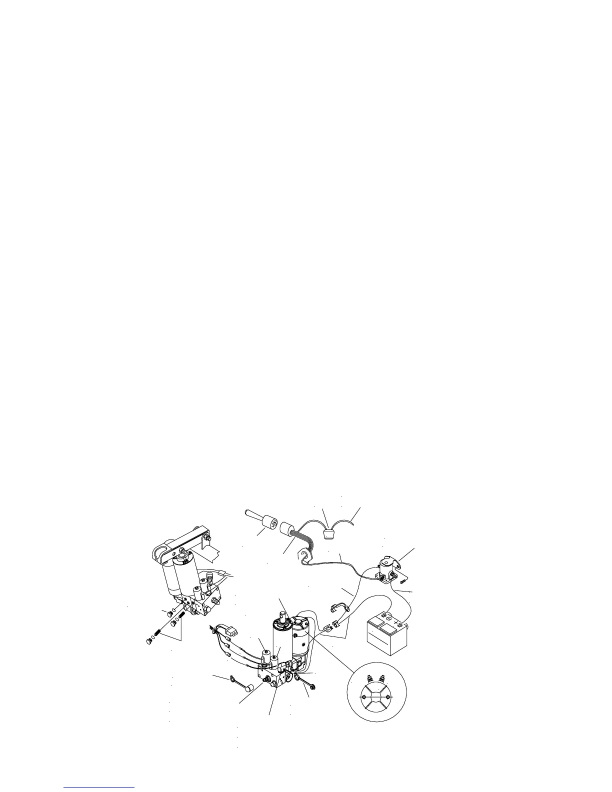
3. The solenoid coils must be on their proper valve. The “C” coil (green wire) must be next to angling fittings. The “B” coil
(red wire) is located to the front of the Electro Lift
®
Unit. The “A” coil (black wire) is smaller and is located on the back side
of the unit. (See Drawing).
TESTING TIPS
Many tests do not require removing the Electro Lift
®
unit from the vehicle. However, more thorough testing can be per-
formed using the Meyer Test Stand which allows direct pressure and amperage readings.
1. Using a screwdriver or other small tool to check for magnetism of the solenoid coils “A”, “B”, “C”. Place the tool on the nut
securing the coil and have an assistant operate the switch. You should feel strong magnetic attraction.
2. Use a test light or volt meter to determine whether there is power at the harness or switch. The current 22154 Electro-Touch
Control has been redesigned. Note: The Electro-Touch Controller now has raised buttons and its circuitry has been changed
from analog to digital, functions have not changed. For troubleshooting for power at the solenoids do not disconnect wires.
To check for power, prick the wire through the insulation for testing. The control knows when a short or an open connection
occurs and will go into overload mode for the function being activated. To reset the controller turn the switch on and off. The
Electro-Touch Control will not operate if not wired properly. Controller must be grounded, Orange wire from switch harness
attaches to the negative terminal of the battery. Reference Form 1-795 for wiring diagram.
3. When determining AMP draw of the motor, always obtain the highest value possible, i.e, at maximum raise or maximum
angle with motor running.
4. Proper rotation for the 3” motor (American Bosch) is indicated by an arrow located on top side of the (Part # 15026) pump.
5. The pump shaft of a good pump can be turned smoothly using two fingers. If it can’t be turn easily, the pump is too tight and
must be replaced.
6. Pump pressure can be measured at an angle hose (note pressure at full angle) or in the pressure filter port (an adaptor is
necessary for the filter port). Note: The E-57 Electro Lift
®
Unit has a non adjustable pressure relief valve.
7. Flush the complete system including unit, hoses and power angling rams with Meyer Hydra-Flush™ Fluid M-2.
-24-
To Motor
B
A
T
T
E
R
Y
NE
G
P
O
S
20A
Motor Solenoid
(Must be grounded)
22092
White
15680
To Ignition Switch
(Accessory Side)
-
+
A2
D1
FUSE
To Pa s s e n g e r S i de
Power Angling Ram.
(Angle Left)
To D r i v e r 's S i d e
Power Angling Ram.
(Angle Right)
R
E
D
"
B
"
G
R
E
E
N
"
C
"
B
L
A
C
K
"
A
"
"A"
Pressure Relief
Filler Plug
"C"
"B"
D
R
A
I
N
P
L
U
G
D
R
A
I
N
F
I
L
T
E
R
S
To Positive
Battery Terminal
Ground
Coupler
Weather Cap
Coupler
Weather Plug