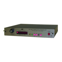
MFJ-1270C/1274C MANUAL APPENDIX B: CALIBRATION
Page 235
Test equipment needed: Frequency Counter and probe and oscilloscope with
probe.
1. Install push-on jumpers on JMP 4 and JMP 7.
2. Verify a push-on jumper is installed on JMP 8.
3. In the following procedure all frequencies are to be set to within +/- 2 HZ.
4. Place the frequency probe at JMP 9 pin 1. This is the top pin.
5. Place the oscilloscope probe on top pin of JMP 10.
6. Set dip switch #7 ON.
7. Set one of the dip switches 1 thru 5 to the Computer Baud Rate which
appiles to the baud rate being used on the computer.
8. Push the
VHF/HF
switch to the
VF
position.
9. Initiate the calibration mode by typing:
CALIBRATE
<ENTER>
10. Now the modem must be keyed up. Do this by pressing the
K
key.
11. Check the voltage on pin 9 of U16. Press the
SPACE BAR
until this pin
indicates -5 VDC.
12. Adjust R78 to where the frequency counter indicates 1200 Hz +/- 2 Hz.
13. Press the
SPACE BAR
until pin 9 of U16 indicates +5 VDC.
14. Adjust R77 to where the frequency counter indicates 2200 Hz,+/- 2 Hz.
15. Press the
D
key.
16. Set the
TIME/DIV.
scale on the scope to
1 MS/DIV
and the
VOLT/DIV
scale to
5 V/DIV.
Connect the scope probe to the toppin of JMP 10.
17. Adjust R79 so that signal on the scope shows a 50% duty cyclesquare
wave. The square wave should be uniform in width ( i.e hightime is equal to the
low time ). The pulse duration of the high time and the low time is
approximately 2.4ms. The CON and STA LEDS may blink simutaneously.
18. Type Q to quit the calibration routine.
METHOD II
The below procedure needs no test equipment, and is very accurate if done
properly. Be sure to follow each step carefully. If any problems arise, please go
back and check the preceeding step, to make sure it worked.
This procedure is a three (3) step process. The three steps areas follows:
1. Center the modulator tones over the required modem center frequency
(Fc).


 To Next Page