MFJ-269D Instruction Manual LF/HF/VHF/UHF SWR Analyzer
22
5.5.1.3 DTF Antenna Length
To measure the electrical length of wire antennas (longwires, dipoles, Beverages), connect through a
good broadband matching transformer -- or by connecting directly to the analyzer's Antenna port.
To ensure accuracy, avoid using any appreciable lengths of feedline (more than 1/32 wl) between the
analyzer and the antenna. While measurements can be made with a transmission line connected between
the antenna and analyzer, false zero reactance crossings will be introduced from line mismatch.
Watching the SWR meter will help you weed-out false reactance nulls when measuring antennas through
a transmission line.
To determine antenna length, treat the antenna like a transmission line, following the procedure for
measuring Distance To Fault. For a dipole, your result will be the electrical length of one leg. For a
longwire or Beverage, it will be electrical length for the entire antenna.
5.5.1.4 DTF Measurement Procedures
Distance to Fault is the first measurement mode in Advanced-2. To enter the mode, press and hold the
Mode and Gate buttons until Advanced-2 appears on the screen. From other Modes, step through the
menu holding the Mode and Gate button.
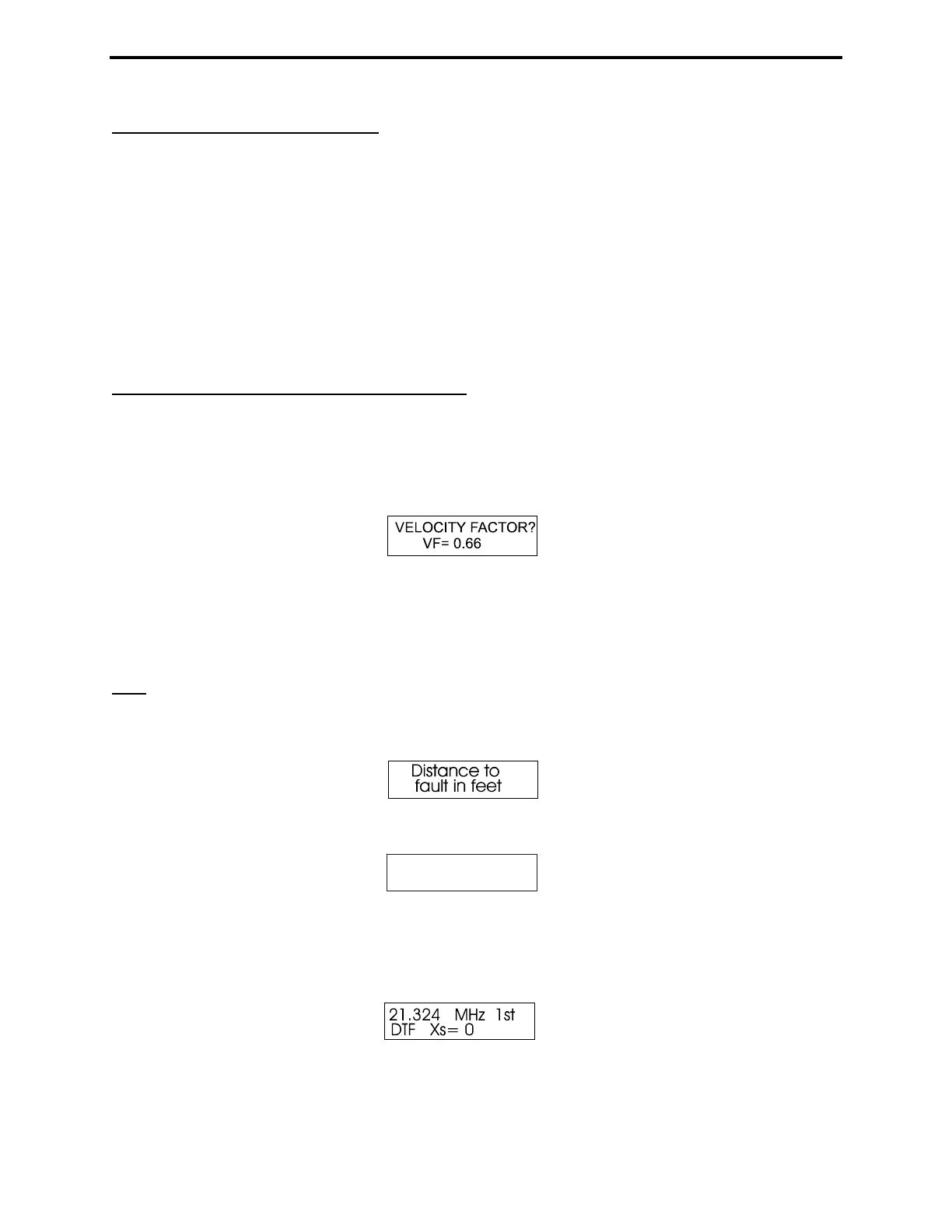
The first menu that appears is:
The Gate button increases Vf, Mode decreases it.
1. Set the Vf to the factory specified velocity factor of the transmission line. This data is required to for
Physical Length calculations that will be displayed later. For Electrical Length in Feet, set Vf to unity
(1.00).
Note: An Incorrect Vf setting will not cause an errors in electrical measurements such as Length in
Degree. However it will cause an error in physical length calculations, such as Dist. to Fault .
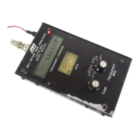
2. After setting the Vf, press Gate and Mode simultaneously to lock-in the value. The display indicates:
and after a few seconds changes to (sample screen):
15.814 MHz 1st
DTF Xs= 51
Note that 1st is flashing on and off. This display is prompting you to use Tune to find the frequency
where the Impedance Meter shows the lowest reading for Xs (as close to Xs=0 as possible). When you
find that frequency, press and hold Gate until the flashing 1st on the display stops flashing. Then release
Gate quickly.
The display now indicates the first frequency data point and the blinking 1st will change to a blinking
2nd: