MFJ-993 IntelliTuner Automatic Antenna Tuner Instruction Manual
© 2003-2004 MFJ Enterprises, Inc.
7
Interface cables for Alinco and Icom radios are available from MFJ Enterprises, Inc. Interface cables
for compatible Kenwood and Yaesu radios will be available in the future. The MFJ-5124A interface
cable provides power and control between an Alinco radio and the MFJ automatic tuner. Supported
Alinco radios are DX-70, DX-77, and any Alinco radio that supports the Alinco EDX-2 tuner.
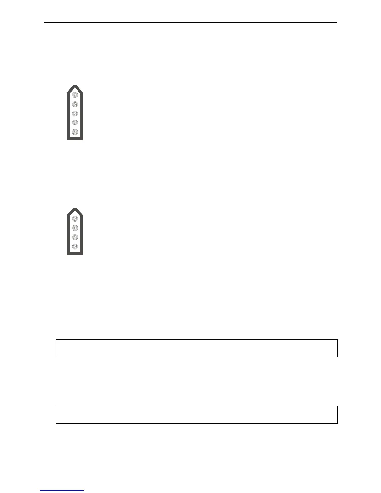
Pin 3 (Key) connects to the Tip of 3.5 mm Stereo Phone Plug.
Pin 5 (Start) connects to the Ring of 3.5 mm Stereo Phone Plug.
Pin 2 (+13.8V) connects to the Center Pin of Power Plug.
Pin 1 (Ground) connects to the Sleeves of both 3.5 mm Stereo Phone Plug and Power Plug.
Pin 4 is not connected.
Figure 4. Alinco Interface Cable.
The MFJ-5124I interface cable provides power and control between an Icom radio and the MFJ
automatic tuner. Supported Icom radios are IC-706, IC-707, IC-718, IC-725, IC-728, IC-736, IC-738,
IC-746, IC-756, IC-765, IC-775, and any Icom radio that supports the Icom AH-3 and AH-4 tuners.
Push and hold the radio’s [TUNER] button for two seconds to start the tuning process. Push
[TUNER] quickly to bypass the tuner.
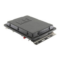
Pin 1 (Key) connects to the Tip of 3.5 mm Stereo Phone Plug.
Pin 2 (Start) connects to the Ring of 3.5 mm Stereo Phone Plug.
Pin 3 (+13.8V) connects to the Center Pin of Power Plug.
Pin 4 (Ground) connects to the Sleeves of both 3.5 mm Stereo Phone Plug and Power Plug.
Figure 5. Icom Interface Cable.
• Transmitter: SO-239 connector for coax cable from transmitter or transceiver.
• Balanced Line: Two binding posts for connecting balanced line antennas. To use balanced line
antenna, install a jumper as shown to the WIRE binding post.
• Wire: Binding post for connecting single wire antennas. Notice the WIRE binding post is internally
connected to the ANTENNA 1 connector.
Note: To use the WIRE binding post, make sure to remove the antenna, if any, from the
ANTENNA 1 connector.
• Ground: Wing-nut terminal for RF ground wire connection.
• Antenna 1: SO-239 connector for coax cable from antenna. Notice the ANTENNA 1 connector is
internally connected to the WIRE binding post.
Note: To use the ANTENNA 1 connector, make sure to remove the jumper and wire antenna, if
any, from the WIRE binding post.
• Antenna 2: SO-239 connector for coax cable from antenna.