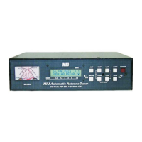
MFJ-993 IntelliTuner Automatic Antenna Tuner Instruction Manual
© 2003-2004 MFJ Enterprises, Inc.
25
Wattmeter Calibration
To calibrate the meter needles, you will need a Phillips screwdriver and a tuning tool or small flat blade
screwdriver.
WARNING: Never operate the MFJ-993 with its cover removed; dangerous voltages and
currents can be present during operation. Never exceed tuner specifications.
Note: The trimmers involved in this calibration are located on the circuit board behind the front
panel; do not confuse these with the SWR bridge trimmers.
1. Turn off the power to the tuner and the transmitter.
2. Remove the cover from the tuner (12 screws) with a Phillips screwdriver.
3. Press and hold both the [TUNE] and [C-UP] buttons while turning the power on.
4. A message
CAL FWD METER TO 100 WATTS will display and both meter needles will bounce.
Use a small flat blade screwdriver and adjust the FWD trimpot R75, located behind the display, to set
the forward needle to the 100-watt mark.
5. Press the [TUNE] button to calibrate the reflected needle.
6. A message
CAL REF METER TO 20 WATTS will display. Adjust the REF trimpot R76, located
behind the display, to set the reflected needle to the 20-watt mark.
7. Press the [TUNE] button to end calibration.
8. Turn off the tuner power and secure the cover back onto the tuner.
SWR Bridge Calibration
To calibrate the SWR Bridge, you will need a transmitter capable of 100 watts output, a precise calibrated
wattmeter, a 50-ohm dummy load, three 50-ohm SO-239 coax cables, a Phillips screwdriver, and a tuning
tool or small flat blade screwdriver.
WARNING: Do not touch anything inside the tuner during operation! Serious, painful RF
burns can result.
WARNING: Never operate the MFJ-993 with its cover removed; dangerous voltages and
currents can be present during operation. Never exceed tuner specifications.
Note: The trimmers involved in this calibration are located on the main circuit board in front of the
TRANSMITTER connector; do not confuse these with the SWR/wattmeter trimmers.
1. Turn off the power to the tuner and the transmitter.
2. Remove the cover from the tuner (12 screws) with a Phillips screwdriver.
3. Connect the 50-ohm dummy load to the ANTENNA 1 connector; connect the wattmeter between the
transmitter and the TRANSMITTER connector on the tuner.
4. Turn on the power to the transmitter. Using a frequency in the middle of the HF band, such as 7.253
MHz, for calibration is recommended.
5. Press and hold both the [TUNE] and [L-UP] buttons while turning the tuner power on.