51033211EN/AC - Page 17
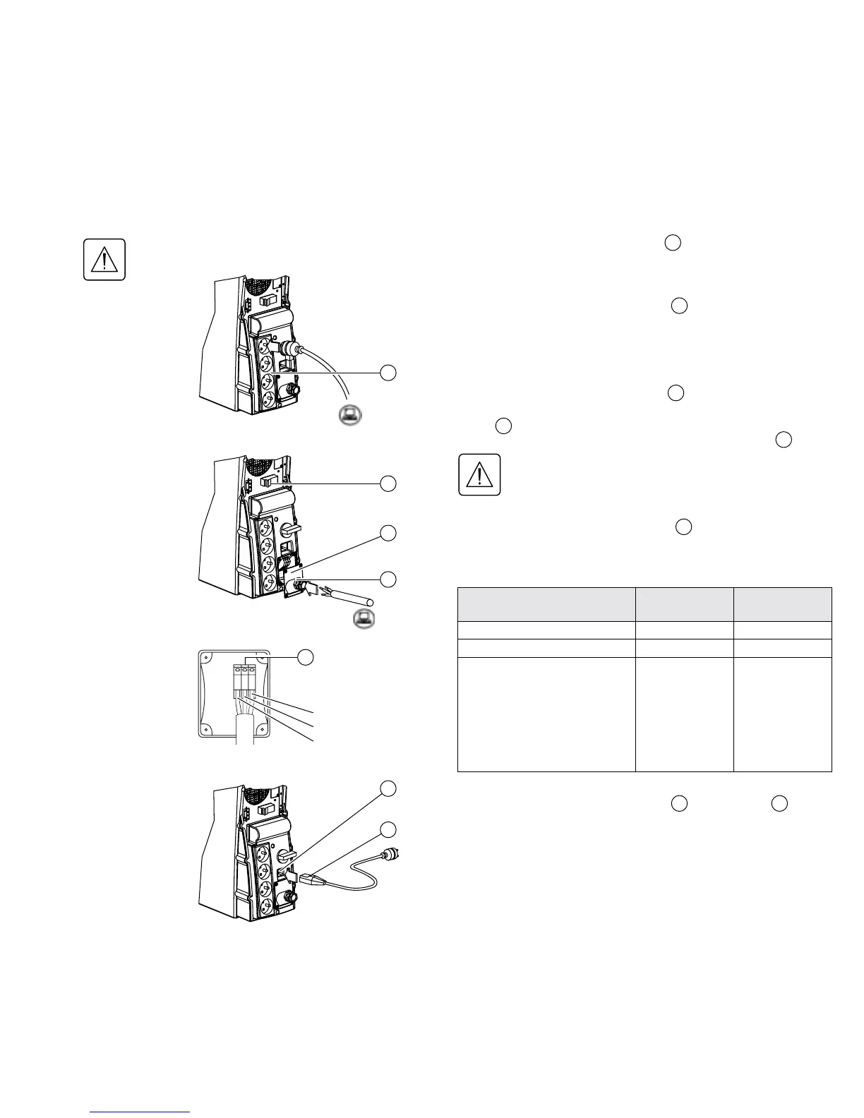
2. Installation
Before carrying out any connections, check that the battery circuit breaker is OFF
and that the electrical power cord to the AC-power source is disconnected.
Connection of equipment to outlets
Plug your equipment into the outlets .
Connection of equipment to a terminal block:
This type of connection must be carried out by qualified
electrical personnel.
1. Remove the terminal-block cover .
2. Insert the cable supplying the equipment through the cable
clamp .
3. Connect the three wires to the output terminal block .
Always connect the earthing wire first.
4. Remove the terminal-block cover.
5. Tighten the nut on the cable clamp .
The overall cable diameter and the cross-sectional area
of the three wires depends on the UPS rating.
Connection to the AC-power source:
1. Connect the electrical power cord to the socket
for connection to AC-power source.
2. Connect the other end of the electrical power cord
to an AC-power outlet.
2
29 1
5
33
33
Hot swap
8
32
8
2
32
33
1
Earthing wire
29
5
Phase
Neutral
Cable diameter
Cross-sectional area of each wire
Pulsar EXtreme
2000
Pulsar EXtreme
3000
From 9 to 12 mm From 9 to 12 mm
1 to 4 mm
2
1,5 to 4 mm
2
Recommended upstream
circuit breaker
◗ Nominal rating
(47 to 63Hz, 230V)
◗ Maximum rating
(47 to 63Hz, 187V)
C60N 10A 2P
(maximum line
current = 9A)
C60N 16A 2P
(maximum line
current = 11A)
C60N 16A 2P
(maximum line
current = 13A)
C60N 20A 2P
(maximum line
current = 16A)
Output terminal block