Table Recommended upstream protective device sizing *
1-2
INPUT VOLTAGE
40 kVA 50 kVA 65 kVA 80 kVA 100 kVA 125kVA 150kVA
208 150 175A 225A 300A 350A 450A 500A
220 150 175A 225A 300A 350A 450A 500A
480 70 80A 100A 125A 150A 200A 225A
600 60 70A 80A 100A 125A 150A 200A
* Size determined using nominal input currents.
NOTES:
1. Total width, weight, and heat loss are for system line-up excluding battery cabinets.
2. Table does not include battery data; refer tot the installation drawings supplied with
your equipment.
The steps to be followed are:
• Placement of the UPS and associated equipment
• Connection of input power, output power, and control
cables
Installation of UPS equipment must be handled by skilled
technicians and electricians familiar with the special
requirements of high-energy electrical equipment. We
strongly recommend contracting MGE Customer Support
Services for start-up of the installed Comet UPS system. Do
not allow unqualified personnel to handle or operate the
Comet UPS.
Refer to the installation drawings for proper placement and
connections of auxiliary cabinets.
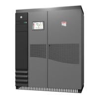
Move the Comet UPS, battery cabinets (if any), and auxiliary
cabinets (if any), to their final location (see Figure 2-1). For
cabinets installed adjacent to each other, alignment is critical
to properly install the mechanical and cable interconnections.
Allow at least 36 inches clearance above all cabinets for
maintenance and cooling.
2.5.1 Placement
2.5 Installation
Procedures
2 — 4 Installation 86-160310-00
Comet 40 - 150 kVA Uninterruptible Power System




 To Next Page