Description - Functionality LDM 210 - LDM 220
128569B 7
Publication, traduction et reproduction totales ou partielles de ce document sont rigoureusement interdites, sauf autorisation écrite de nos services.
The publication, translation or reproduction, either partly or wholly, of this document is not allowed without our written consent. Format 112175C
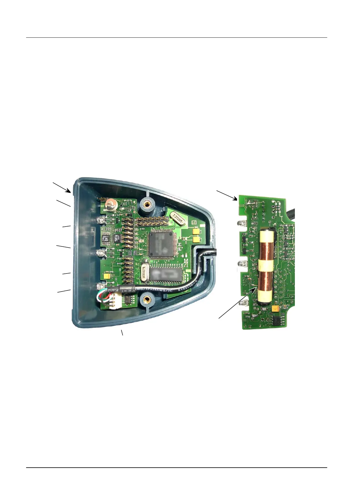
2.2.1 LDM 220 dosimeter reader
The plastic enclosure contains:
The reader PCB UC (1). It includes:
An Antenna (ANT1) located behind the UC (1) card that allows communication with
the dosimeter within a nominal range of 20 to 30 cm. The antenna is attached to the
printed circuit board,
A 5 pin male connector (J1) for the connection to the USB cable,
A 14 pin male connector (J15) for the analog inputs and outputs,
A 14 pin male connector (J16) for the reader configuration mode,
Three bicolor LED's green and red for "Power", "Access" and "Status" (CR2, CR3
and CR4),
A label (2) glued to the enclosure front panel.
An identification label indicating the model and serial number of the Reader.
1
CR4
J16
CR3
1
2
J15
Antenna
CR2
Antenna
(Underside View)
J1
Figure 8 :
LDM 220 enclosure and PCB Description
 Loading...