Description - Functionality LDM 210 - LDM 220
2.3 Operation
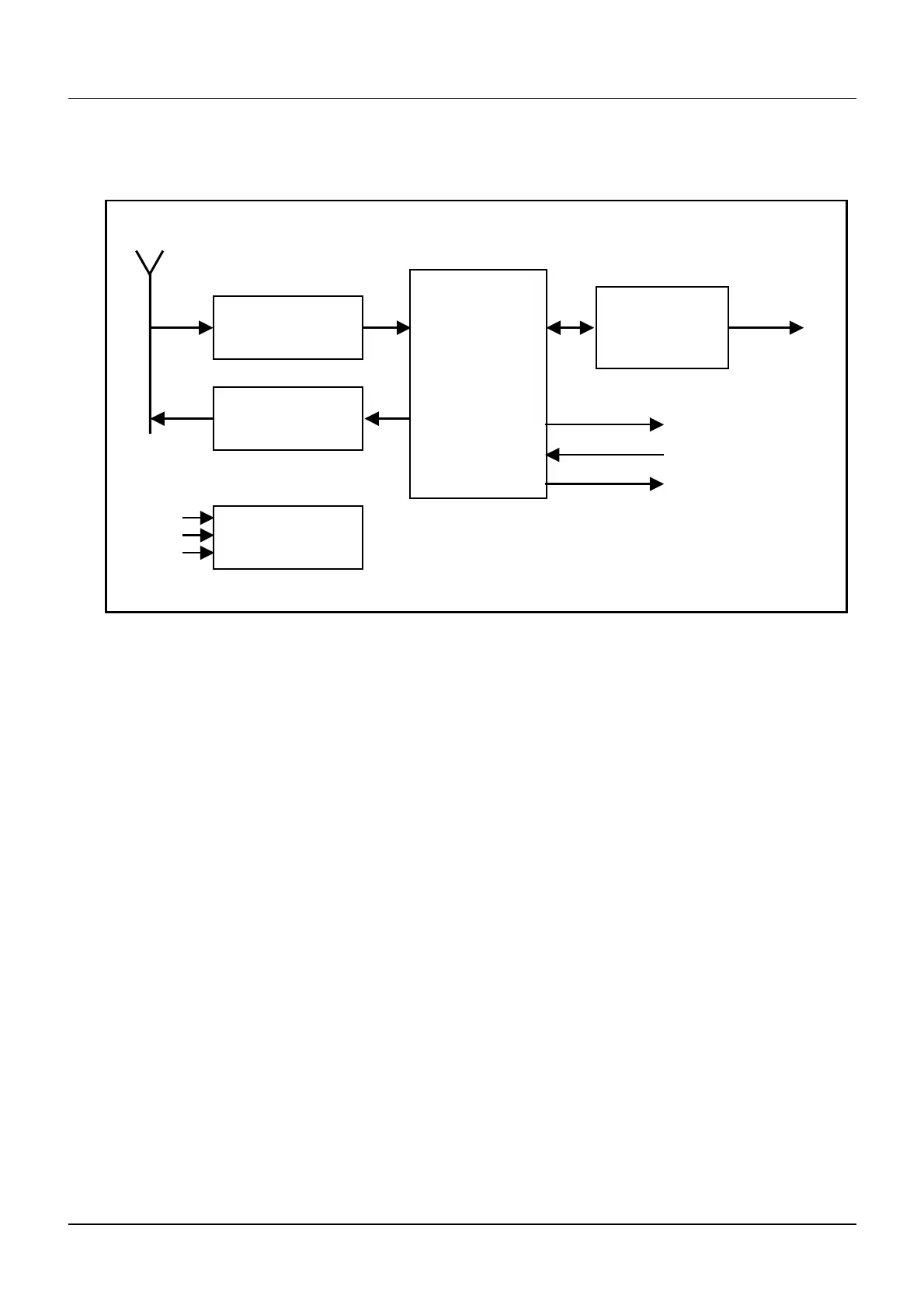
PC link
LED’s
IN DIs
OUT DOs
Antenna
Batteries
Ext. Powe
USB powe
Hands free link with the
dosimeter
RS232 o
USB
Interface
Processor
Reception
link
Emission
link
Power
Figure 10 : LDM 210 and LDM 220 Block Diagram
The following operating modes are defined by the position of jumpers in the J16
connector (see § 3.1, page 12).
Normal Operating Model.
Test Mode.
2.3.1 Normal Operating Mode.
This is the normal operating mode of the reader.
In this mode, the reader functions as a slave of the PC.
It receives commands from the PC.
It searches for a dosimeter.
It executes commands – reading or writing dosimeter parameters or information.
It transmits a report to the PC.
128569B 9
Publication, traduction et reproduction totales ou partielles de ce document sont rigoureusement interdites, sauf autorisation écrite de nos services.
The publication, translation or reproduction, either partly or wholly, of this document is not allowed without our written consent. Format 112175C
 Loading...