6
INSTALLATION: ASSEMBLY AND CONNECTION OF COMPONENTS
––– STEP 5 –––
IMPORTANT!
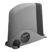
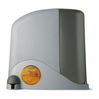
- The following assembly phases show installation of a gearmotor
model SL1SC/SL10SC.
- To ensure correct system operation, mechanical stops must be
mounted on the fl oor or wall at the maximum leaf opening and closing
points. Note - These stops are not supplied in the pack and are not
part of the Mhouse product range.
WARNINGS
• Incorrect installation may cause serious physical injury to those
working on or using the system.
• Before starting automation assembly, make the preliminary
checks as described in STEP 3.
5.1 - INSTALLING THE GEARMOTOR ON THE GATE WITH-
OUT A RACK
If the support surface already exists, the gearmotor should be fi xed on it
directly, using suitable means, such as expansion plugs. Otherwise, to
secure the gearmotor, proceed as follows:
01. Make a suitably-sized foundation pit, according to the required site of
installation; see values shown in fi g. 2;
02. Prepare one or more duct tubes for routing the electric cables (fi g. 5).
Note - Leave tubes longer than 50 cm;
03. Fit two bolts on the foundation plate placing a nut below and above
the plate; the nut below the plate should be tightened as shown in
fi g. 6 so that the threaded section protrudes by approx. 36 mm
above the plate;
04. Before casting the concrete, prepare the foundation plate with the
printed side (position of pinion) facing the gate and positioned as
specifi ed by the values in fi g. 7; then lay the tubes for routing the
cables through the relative hole;
05. Now cast the concrete and place the plate as described in point 04,
ensuring that it is parallel to the leaf and perfectly level (fi g. 8).Wait for
the concrete to set completely;
06. When the concrete is suffi ciently dry (after a few days), remove the 2
upper nuts which will no longer be used;
07. Shorten the cable routing tubes by 30/40 mm;
08. Remove the nut cover on the gearmotor (fi g. 9);
09. Rest the gearmotor on the plate, ensuring that it is perfectly parallel
to the leaf, then slightly lighten the 2 locknuts and washers supplied
(fi g. 10). Tighten the nuts fully down;
10. Manually release the gearmotor (see paragraph 11.3 – User’s guide;
11. Move the gate to the maximum opening position then position the
fi rst section of the rack above the pinion of the gearmotor. The rack
should protrude, with respect to the axis of the pinion, by the value
specifi ed in fi g. 11 (with motor fi xed to left) or fi g. 12 (with motor
fi xed to right); i.e. the space required for the limit switch brackets;
Important! – Leave a clearance of 1 mm between the rack (for all parts)
and the pinion (fi g. 13), so that the weight of the leaf does not exert pres-
sure on the motor.
12. Now fi x the other parts of the rack one after the other; to keep the
rack aligned with the level of the pinion, simply trace the fi xing hole
when the slot is aligned with the axis of the pinion (fi g. 14). Repeat
the same operation at each fi xing point;
13. After fi
xing the last part of the rack, if necessary, cut off the protrud-
ing section; the rack should not protrude from the leaf;
14. Manually complete a number of leaf opening and closing cycles to
ensure that the rack slides smoothly along the pinion throughout the
entire length;
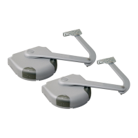
15. Position (approximately) the two [A] limit switch brackets on the rack
(fi g. 15) and manually move the gate for fi nal fi xture.
16. Fix the limit switch brackets as follows:
a) manually move the leaf to the opening position, leaving a distance
of at least 2-3 cm from the mechanical end stop.
b) slide the travel limit bracket on the rack in the opening direction
until the limit switch trips. Then move the bracket forward by at least
2 cm and lock on the rack using the grub screws supplied.
c) perform the same operation to secure the closing limit switch.
17. Manually lock the gearmotor (see paragraph 11.3 - User’s guide).
The electrical connections can now be made (see paragraph 6).
5.2 - INSTALLING THE GEARMOTOR ON THE GATE WITH
AN EXISTING RACK
If the support surface already exists, the gearmotor should be fi xed on it
directly, using suitable means, such as expansion plugs. Otherwise, to
secure the gearmotor, proceed as follows:
Warnings
– Before fi xing the gearmotor, ensure that the existing rack is compatible
with the overall dimensions of the pinion (see fi g. 16).
– Ensure that the distance between the pinion and rack is approx. 12 mm.
01. Make a suitably-sized foundation pit, according to the required site
of installation; see values shown in fi g. 2; Caution! – The foundation
plate must be positioned at 77 mm from the rack.
02. Fit one or more tubes for routing the electric cables (fi g. 5). Note -
Leave tubes longer than 50 cm;
03. Fit two bolts on the foundation plate placing a nut below and above
the plate; the nut below the plate should be tightened as shown in
fi g. 6 so that the threaded section protrudes by approx. 36 mm
above the plate;
04. Before casting the concrete, prepare the foundation plate with the
printed side (position of pinion) facing the gate and positioned as
specifi ed by the values in fi g. 17; then lay the tubes for routing the
cables through the relative hole;
05. Now cast the concrete and place the plate as described in point 04,
ensuring that it is parallel to the leaf and perfectly level (fi g. 8). Wait
for the concrete to set completely;
06. When the concrete is suffi ciently dry (after a few days), remove the 2
upper nuts which will no longer be used;
07. Shorten the cable routing tubes by 30/40 mm;
08. Remove the nut cover on the gearmotor (fi g. 9);
09. Place the gearmotor on the foundation plate, tilting it to facilitate
insertion below the rack (fi g . 18). Slightly tighten the 2 locknuts,
after inserting the washers;
10. If necessary, adjust the gearmotor height (max. 10 mm), using the 4
stud bolts fi tted (fi g. 19). Important! – Leave a clearance of 1 mm
between the rack and the pinion, so that the weight of the leaf does
not exert pressure on the motor.
Where possible, fix the gearmotor without stud bolts, to ensure
increased stability and solid fi xture on the plate;
11. Ensure that the gearmotor is perfectly parallel to the leaf, then fi x it to
the foundation plate, tightening the 2 locknuts fully down;
12. Manually release the gearmotor (see paragraph 11.3 - User’s guide);
13. Manually complete a number of leaf opening and closing cycles to
ensure that the rack slides smoothly along the pinion throughout the
entire length;
14. Fix the [A] limit switch brackets (fi g. 15
) as follows:
a) manually move the leaf to the opening position, leaving a distance
of at least 2-3 cm from the mechanical end stop.
b) slide the travel limit bracket on the rack in the opening direction
until the limit switch trips. Then move the bracket forward by at least
2 cm and lock on the rack using the grub screws supplied.
c) perform the same operation to secure the closing limit switch;
15. Manually release the gearmotor (see paragraph 11.3 - User’s guide).
The electrical connections can now be made (see paragraph 6).
 Loading...