23
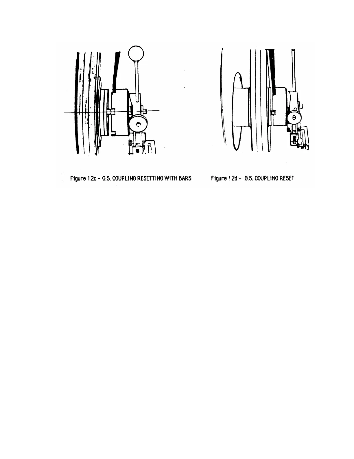
3.6.1 Resetting the G.S. Coupling (Refer to Figures 12c and 12d)
1. Insert a steel bar into a hole in the coupling and a bar in a slot
in the driver.
2. Rotate the bars in opposite directions until the steel balls return
to original position. Be sure slots in the coupling line up with
the cams on the V-belt sheave (See Figure 12c and 12d). If
not, the coupling will not reset.
3. Remove bars and reset limit switch. The conveyor and bowl
are now again coupled together.
3.6.2 Testing G.S. Coupling for proper release force (Refer to Figure 13)
1. Place G.S. Coupling torque measuring adapter over coupling
assembly. Insert pin in adapter hole through to the hole in the
coupling.
2. Place torque wrench socket fitting into socket on adapter.
3. With G.S. Coupling engaged as in Section 3.6.1 turn clockwise
and not torque reading at disengagement. Repeat four (4)
times. Note smallest reading. This reading should be between
50 and 60 ft.lbs (67.1-81.3 Nm).
4. Repeat step 3 in the counterclockwise direction. Readings
should be the same.
 Loading...