63
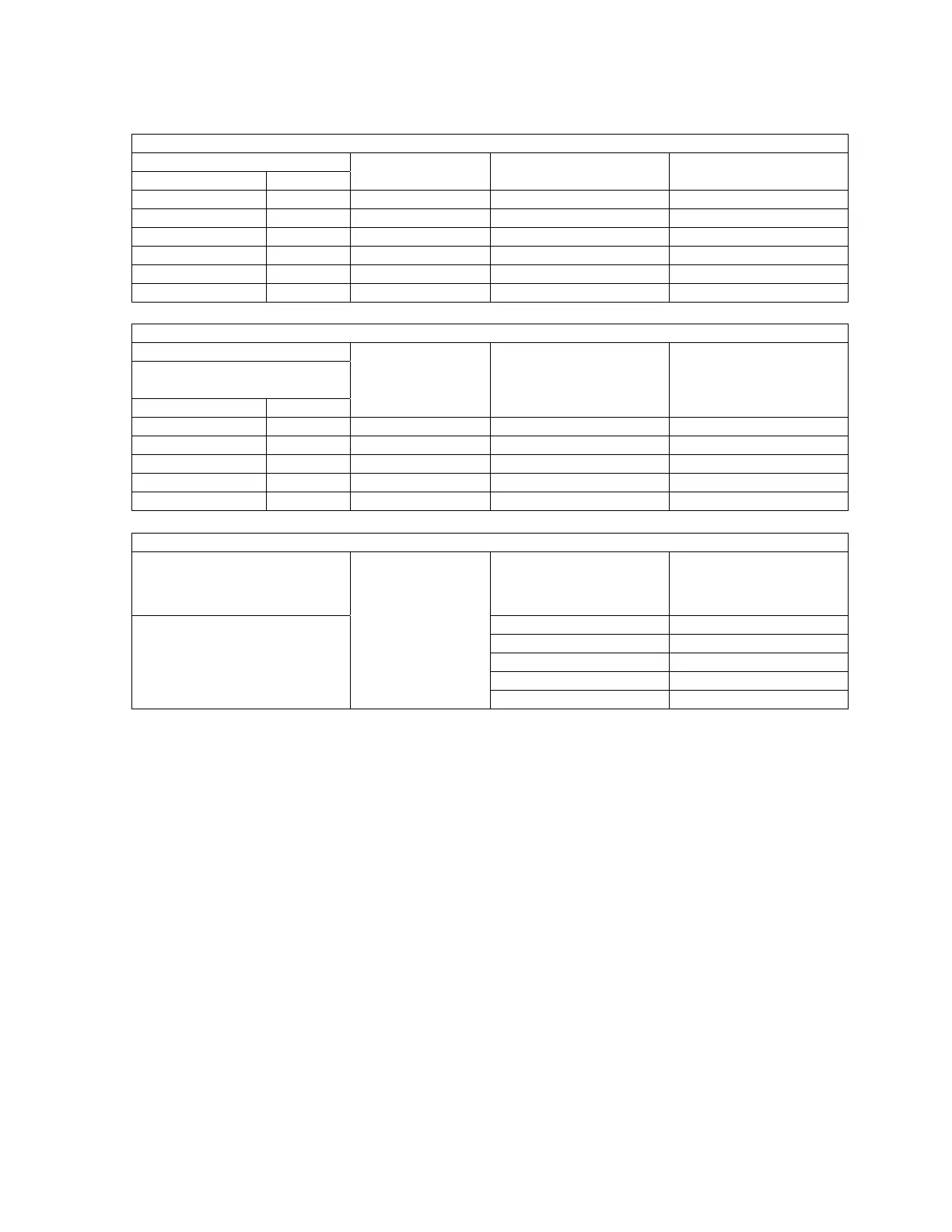
Table 1
Difference
(a-b) mm In.
Qty. Part No. Tmm
11.0-11.9 .43-.47 0
12.0-12.9 .47-.51 1 96-10-418 1
13.0-13.9 .51-.55 1 96-10-421 2
14.0-14.9 .55-.59 1 96-10-418
1 96-10-421 3
15.0-15.9 .59-.63 2 96-10-422 4
Table 2
Difference
(9.4 + d)-e mm
(.370 + d)-e In.
Mm In.
Qty. Part No. Tmm
0-0.4 0-.016 1 96-10-419 1
0.5-0.9 .02-.035 1 96-10-420 1.5
1.0-1.4 .04-.06 2 96-10-419 2
1 96-10-419
1.5-1.9 .06-.075 1 96-10-420 2.5
Table 3 Shim Thickness
Gearbox end of conveyor Part No. Tmm
96-10-418 1
96-10-421 1.5
2
96-10-419
Feed End of Conveyor
96-10-420 2.5
Adjustment of space between conical part of bowl and conveyor and axial clearance between
bowl and conveyor.
1. In addition to normal procedure when changing conveyor, remove the small end
piece.
2. Place the conveyor in the bowl shell so that it touches the cone.
3. Measure the distances a,b,d and e as shown in Diagram 9.
4. Calculate the difference a-b and find in Table 1 the adjusting shim or shims to be
placed at position T between the conveyor big end bore and the bearing arrangement
to give the right space.
5. Calculate the difference (9.4 + d) - e mm and find in Table 2 the adjusting shim or
shims to be placed at position (t) between the conveyor small end bore and the
bearing arrangement to give the right axial space between conveyor and bowl.
Diagram 9 (414 Centrifuge Method for determing adjusting shims)
 Loading...