Unclassified
HMI
2-1
2.1 FAMILIARIZATION WITH EQUIPMENT
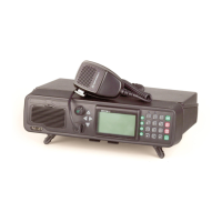
2.2 RM500 FRONT PANEL
The front panel of the RM500 includes a standard MICOM 3 control panel, and the
additional items identified in Figure 2-2.
For a description of the MICOM 3 control panel, refer to Publication 6886867J01,
“Owner’s Guide, MICOM 3E/3T/3R HF-SSB Transceivers”; for indicator functions, refer
to Table 2-2
Table 2-1. RM500 Front Panel Indicators
Indicator Function
VOLT Power supply fault indicator: lights when an internal supply voltage is out of limits. In
this case, the 500W amplifier section cannot operate
OVER
DR
Input overload indicator: lights when the RF drive power supplied to the 500W amplifier
is too high. The 500W amplifier section is bypassed
TEMP Amplifier overheat indicator: lights when the internal temperature is too high. Usually,
this occurs when the air intake or exhaust vents are accidentally obstructed, prolonged
exposure to direct sun radiation, or excessive ambient temperatures.
If the FAILURE indicator flashes while TEMP lights but BYPASS is off, the 500W
amplifier continues transmitting at half power
If the FAILURE and BYPASS indicators light together with TEMP, the 500W amplifier
has switched to the bypass mode
VSWR Excessive VSWR indicator: lights when the 500W amplifier is in the transmit mode to
indicate that the antenna VSWR exceeds the maximum allowed. This may be caused by
a disconnected feed cable, an improperly installed or incorrectly tuned antenna, or as a
result of damage to the antenna or to its feed cable
FAILURE PA failure indicator:
Lights when a critical fault in the 500W amplifier section prevents its operation. In this
case, BYPASS also lights, to indicate that the 500W amplifier is bypassed
Flashes when an operational problem, for example, high temperature, excessive drive
power or excessive VSWR activates the corresponding protection circuits
TX Transmission mode indicator: lights when the 500W amplifier operates in the transmit
mode
BYPASS Bypass mode indicator: lights when the 500W amplifier is bypassed. The amplifier is
normally bypassed when the radio is in the receive mode. It is also bypassed when a
fault or abnormal condition prevents its normal operation