Unclassified
HMI
2-4
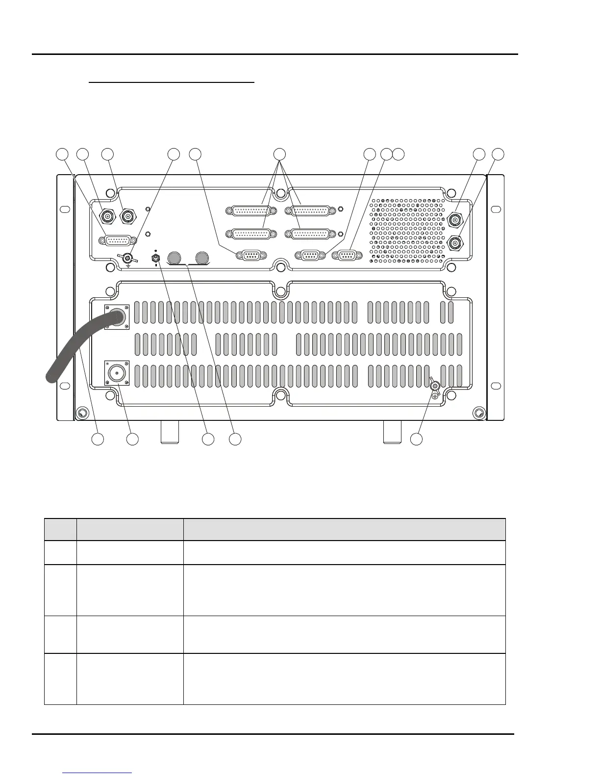
2.4 RM500/RM500R REAR PANEL
Figure 4 shows the rear panel of the RM500 and RM500R. The functions of the various
items are explained in Table 4.
RF OUT
110/220VAC
CC.-J1
CC.-J2
CC.-J3
CC.-J4
ISB PPS-CONT
RX IN
TX IN
ACC. C.H.
REMOTE CONTROL
TX OUT
RX OUT
12 11 10 9 6
53214
7813141516
Figure 2-3. RM500/RM500R Rear Panel
Table 2-2. RM500/RM500R Rear Panel Items
Item Description Function
1 AC Power Cable Connection to AC power source
2 RF OUT Connector UHF connector for connection of feed cable to antenna. Serves as
the radio set RF input in the receive mode, and as the RF output in
the transmit mode
3 REMOTE
CONTROL Switch
Enables/disables remote control by the optional 2-wire control
head
4 REMOTE
CONTROL
Terminals
Connection of 2-wire line to optional 2-wire control head