Unclassified
HMI
2-5/(2-6 Blank)
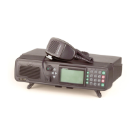
Table 2-2. RM500/RM500R Rear Panel Items (Continued)
Item Description Function
5 Grounding Screw Connection of ground to the 500W power amplifier section
6 RX OUT Connector BNC RF output connector, for connection of unfiltered RF receive
signal to the optional pre/post-selector (PPS) (optional)
7 TX OUT Connector BNC RF output connector, for connection of unfiltered RF
transmit signal to the optional pre/post-selector (PPS) (optional)
8 MKL/DATA
Connector
Optional 9-pin D-type female connector, for connecting to an
MKL Key Loader
9 TUNER CONTROL
Connector
Optional 9-pin D-type female connector, for connecting to an
optional external antenna tuner unit
10 PPS CONTROL
Connector
Connection of control signals to the optional pre/post-selector
(PPS) (optional)
11 ACC-J1 to ACC-J4
Connectors
Four 25-pin D-type male connectors, for connection to external
accessories, for example, voice privacy devices, modems,
vocoders, etc. (see Table 2-1 for pin-out)
12 ISB Connector Optional 9-pin D-type female connector, for connecting to the
additional lines used for the ISB option
13 Grounding Screw Connection of ground to the transceiver section
14 TX IN Connector BNC RF input connector, for connection of filtered RF transmit
signal from the optional pre/post-selector (PPS) (optional)
15 RX IN Connector BNC RF input connector, for connection of filtered RF receive
signal from the optional pre/post-selector (PPS) (optional)
16 ACC. C.H.
Connector
Optional 15-pin D-type female connector, for connecting to the 6-
wire Control Head (option G422AA)
NOTE
Items 8, 9, 10, 12 are installed only when the radio set
is equipped with the corresponding option.