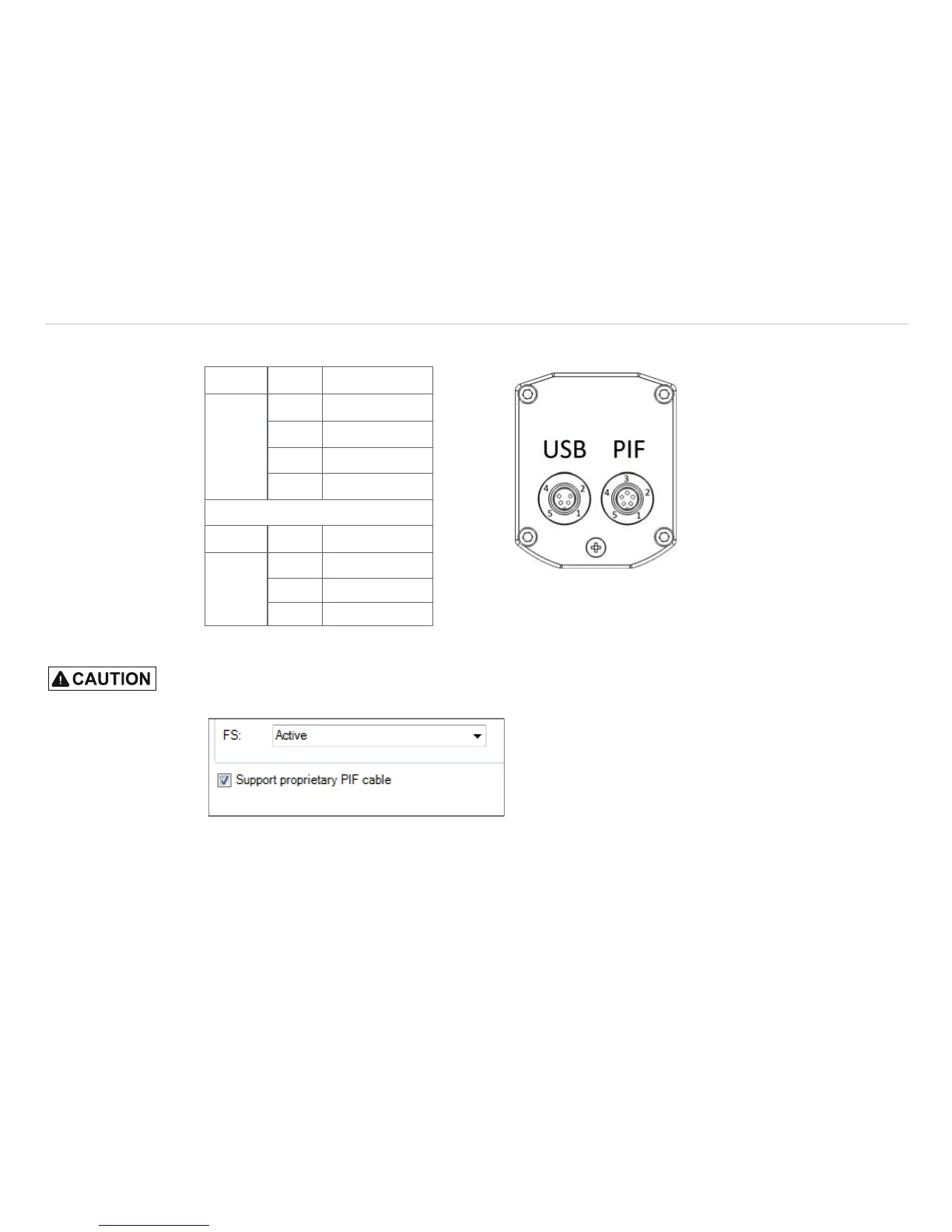
6.1 PIN Assignment of Connectors
PIF 1 INT
2 SDA (I
2
C)
3 SCL (I
2
C)
4 DGND
5 3.3 V (Out)
USB 1 VCC
2 GND
4 D- View on connector side
5 D+
Fig. 23 Pin assignment of rear side of camera
In case you would like to connect the process interface of the camera directly to external hardware
1
(with-
out using the supplied PIF cable) you should activate the field “Support proprietary PIF cable” in the menu
Tools/ Configuration/ Device (PIF) in the TIM Connect software.
Fig. 24 Screen Support proprietary PIF cable
1) We recommend using only a switching contact between INT and DGND as external hardware (button,
relay).
In case of working
with a direct PIF
connection the input
of the PIF is not
protected!
A voltage > 3 V on
the INT pin will de-
stroy the device!