EasyManuals Logo

MICRO-EPSILON TIM 160 User Manual

Default Icon
94 pages
To Next Page IconTo Next Page
To Previous Page IconTo Previous Page
Page #90 background imageLoading...
Page #90 background image
Page 90
Appendix | Process Interface
thermoIMAGER TIM
A 13 Process Interface
A 13.1 Analog Output
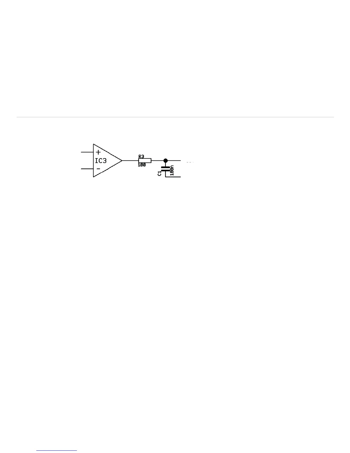
PIF OUT [yellow]
GND [brown]
Fig. 46 Analog output
For voltage measurements the minimum load impedance should be 10 KOhm.
The analog output can be used as a digital output. The voltage for no alarm and alarm on can be set
within the software. The analog output (0 … 10 V) has a 100 Ohm resistor in raw. With a maximum current of
10 mA the voltage drop is 1 V.
Having an alarm LED with a forward voltage of 2 V the analog output value for alarm on should be 3 V as
maximum.

Table of Contents

Other manuals for MICRO-EPSILON TIM 160

Questions and Answers:

Question and Answer IconNeed help?

Do you have a question about the MICRO-EPSILON TIM 160 and is the answer not in the manual?

MICRO-EPSILON TIM 160 Specifications

General IconGeneral
BrandMICRO-EPSILON
ModelTIM 160
CategorySecurity Camera
LanguageEnglish

Related product manuals