6.2 Process Interface
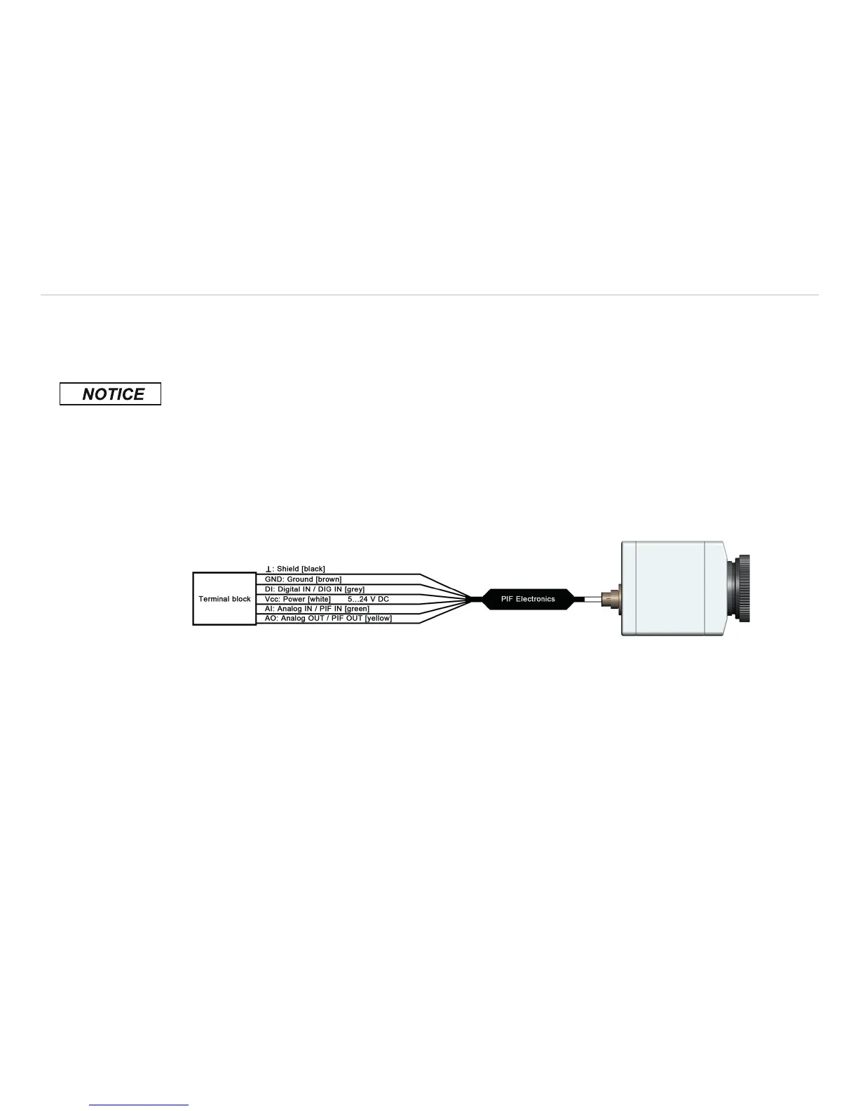
The TIM is equipped with a process interface (cable with integrated electronics and terminal block), which
can be programmed via the software as an Analog Input (AI) and Digital Input (DI) in order to control the
camera or as an Analog Output (AO) in order to control the process. The signal level is always 0 – 10 V.
Please make sure that the process interface (electronics within cable as well as industrial interface) is pow-
ered separately (5 - 24 VDC).
> With no external power supply the PIF will not work
The process interface can be activated choosing the following options:
Analog Input (AI): Emissivity, ambient temperature, reference temperature, flag control, triggered re
cording, triggered snapshots, triggered line scanner, uncommitted value
Analog Output (AO): Main area temperature, internal temperature, flag status, alarm, fail-safe
Digital Input (DI): Flag control, triggered recording, triggered snapshots, triggered line scanner
Fig. 25 Configuration process interface (PIF)