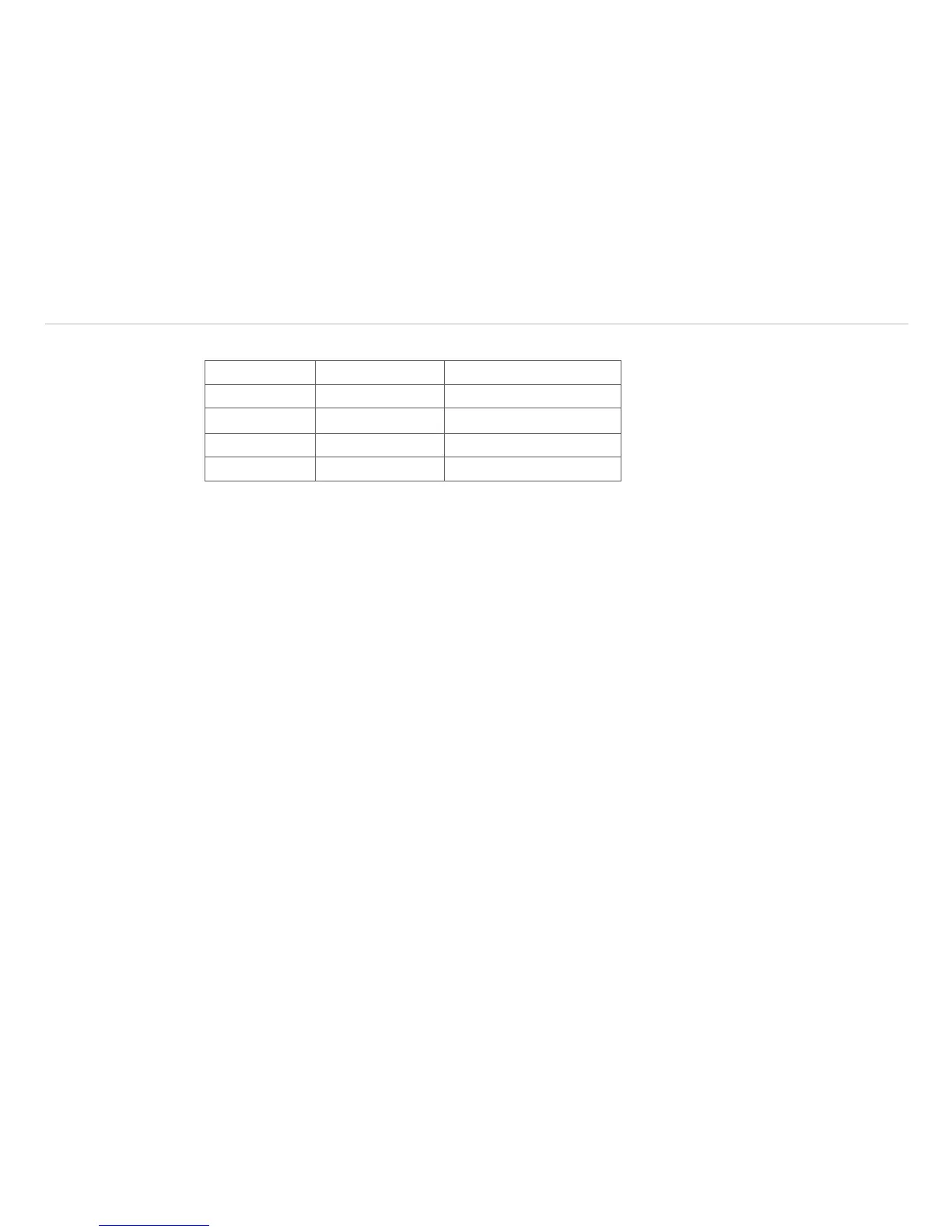
The standard process interface offers the following inputs and outputs:
Designation Description max. range
1/
status
AI Analog input 0 - 10 V
DI Digital input 24 V
AO Analog output 0 - 10 V
Alarm output 0/ 10 V
The voltage levels for the DI are: LOW = 0 ... 0.6 V / HIGH = 2 ... 24 V.
6.3 Industrial Process Interface (Optional)
For use in industrial environment an industrial process interface with 500 VAC
RMS
isolation voltage between
TIM and process is available (connection box with IP 65, 5 m, 10 m or 20 m standard or high temp cable for
camera connection, terminal for process integration), see Chap. A 8 (Industrial Process Interface).
6.4 USB Cable Extensions
The maximum USB cable length is 20 m. For greater distances between TIM and computer or for stand-alone
solutions you should use the optional TIM NetBox or the USB-Server Industry Isochron, see Chap. A 1, see
Chap. A 9.
1) Depending on supply voltage; for 0 - 10 V on the AO the PIF has to be powered with min. 12 V.