The Microchip CAN Bus Analyzer is a compact, low-cost tool designed for developing and debugging high-speed CAN networks. It supports CAN 2.0b and ISO 11898-2 standards, allowing for transmission rates up to 1 Mbit/s. The device offers a broad range of functions suitable for various market segments, including automotive, marine, industrial, and medical.
Function Description:
The primary function of the CAN Bus Analyzer is to monitor and debug CAN networks. It provides an easy-to-use Graphical User Interface (GUI) that allows users to view and log both received and transmitted messages from the CAN bus. Additionally, the tool enables the transmission of single or periodic CAN messages onto the network, which is highly beneficial during development and testing phases.
The device offers a "Trace" feature with two types of windows: "Fixed" and "Rolling."
- The Rolling Trace window displays CAN messages sequentially as they appear on the CAN Bus. It shows the ID (Extended or Standard), Data Length Code (DLC), data bytes, timestamp, and the time difference from the last received message, regardless of the CAN ID.
- The Fixed Trace window displays CAN messages in a fixed position. Messages are updated, and the time delta is based on the previous message with the same CAN ID.
The "Transmit" feature allows users to interact with the CAN Bus by sending messages. Users can input the ID (Extended or Standard), DLC, and data bytes for single messages or configure periodic transmissions. The transmit window supports sending a maximum of nine separate and unique messages, either periodically or with a limited "Repeat" mode. In "Repeat" mode, messages are sent at a periodic rate for a specified number of repeats.
The "Hardware Setup" window allows users to configure the CAN Bus Analyzer for communication on the CAN Bus. This includes setting the CAN bit rate and controlling the bus termination.
Important Technical Specifications:
- CAN Standards Supported: CAN 2.0b and ISO 11898-2 (high-speed CAN).
- Transmission Rates: Up to 1 Mbit/s.
- Connectivity:
- Mini-USB connector for communication with a PC and optional power supply.
- 9-24 Volt power supply connector for external power.
- DB9 connector for the CAN Bus.
- Screw terminal interface for direct access to CANH and CANL pins, and CAN TX and CAN RX pins.
- Termination Resistor: Software controllable 120 Ohm CAN Bus termination.
- Microcontrollers: Utilizes PIC18F2550 and PIC18F2680 microcontrollers.
- Software Requirements:
- Windows® XP operating system.
- .NET Framework Version 3.5.
- USB Serial Port.
- Kit Contents:
- CAN Bus Analyzer Hardware.
- CAN Bus Analyzer Software (including firmware for PIC18F2550 and PIC18F2680 in Hex files, and the PC Graphical User Interface).
- USB mini-cable.
Usage Features:
- Easy-to-use GUI: The PC-based Graphical User Interface simplifies monitoring and debugging.
- Trace Window: Provides a clear, readable display of CAN Bus traffic, including ID, DLC, data bytes, and timestamps.
- Transmit Window: Allows for flexible transmission of single or periodic CAN messages with configurable IDs, DLCs, and data.
- Hardware Configuration: The "Hardware Setup" window enables users to set the CAN bit rate and control the 120 Ohm termination resistor via the GUI.
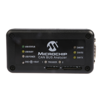
- Status LEDs:
- USB Status: Indicates USB connection status (USB STATUS, USB BUSY, USB POWER).
- CAN Traffic LEDs: Shows actual RX (receive) and TX (transmit) CAN Bus traffic from the high-speed transceiver.
- CAN Bus Error LED: Displays the CAN Bus Analyzer's error state (Error Active - Green, Error Passive - Yellow, Bus Off - Red).
- Flexible CAN Bus Connection: Can be connected to a CAN network using either a DB9 connector or screw-in terminals.
- Direct Pin Access: Screw terminals provide direct access to CANH/CANL and CAN TX/RX pins for connecting an oscilloscope or other diagnostic tools without modifying the wire harness.
Maintenance Features:
- Firmware Upgradability: The device's firmware can be upgraded to match newer PC software versions. This involves importing Hex files into MPLAB® IDE and programming the PIC® MCUs.
- Software Updates: Microchip provides online support and updates for the CAN Bus Analyzer software. Users are encouraged to refer to the Microchip website for the latest documentation and software releases.
- Error Messages: The GUI provides specific error messages with possible solutions to assist users in troubleshooting issues related to firmware, communication, or data input. Examples include errors for invalid ID, DLC, data, period, or repeat field values, and issues with logging data.
- Customer Support: Microchip offers assistance through distributors, local sales offices, Field Application Engineers (FAEs), and technical support via their website.
- Product Change Notification Service: Users can subscribe to receive email notifications regarding changes, updates, revisions, or errata related to the product.