CAN Bus Analyzer User’s Guide
DS50001848D-page 20
2009-2022
Microchip Technology Inc. and its subsidiaries
3.4 HARDWARE SETUP FEATURE
To activate the Hardware Setup window, select “HARDWARE SETUP” from the main
Tools menu.
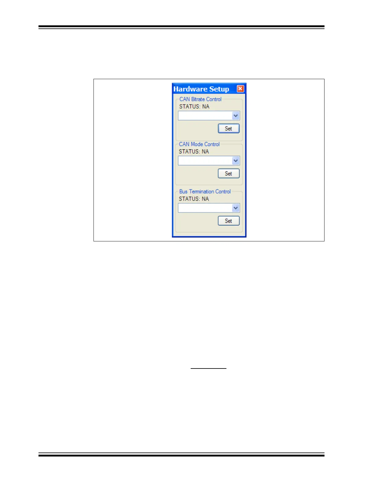
FIGURE 3-5: HARDWARE SETUP WINDOW
The Hardware Setup window allows the user to set up the CAN Bus Analyzer for com-
munication on the CAN Bus. This feature also gives the user the ability to quickly test
the hardware on the CAN Bus Analyzer.
To set up the tool to communicate on the CAN Bus:
1. Select the CAN bit rate from the drop-down combo box.
2. Click the Set button. Confirm that the bit rate has changed by viewing the bit rate
setting on the bottom of the main CAN Bus Analyzer window.
3. If the CAN Bus needs the termination resistor active, then turn it on by clicking
the Turn On button for the Bus Termination.
Test the CAN Bus Analyzer hardware:
1. Ensure that the CAN Bus Analyzer is connected. You can confirm this by viewing
the tool connection status on the status strip on the bottom of the main CAN Bus
Analyzer window.
2. To confirm that the communication is working between the USB PIC
®
MCU and
the CAN PIC MCU, click on the Help->About
main menu option to view the
version numbers of the firmware loaded into each PIC MCU.