CAN Bus Analyzer User’s Guide
DS50001848D-page 10
2009-2022
Microchip Technology Inc. and its subsidiaries
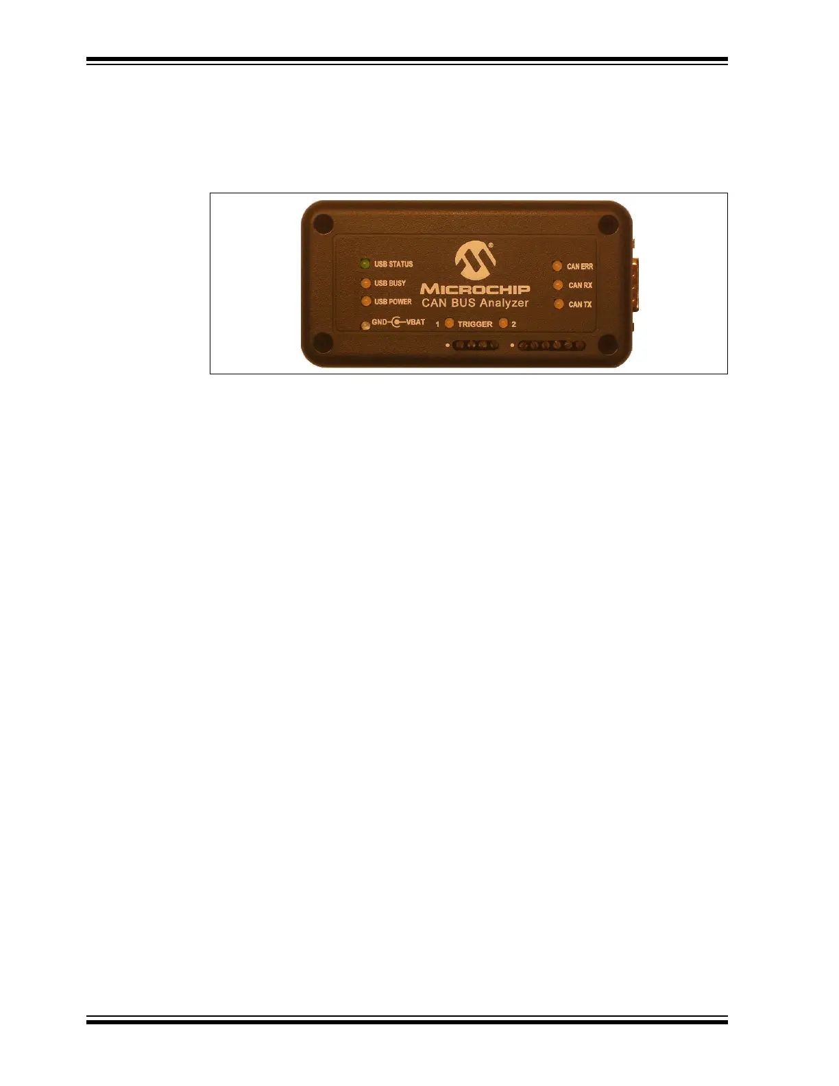
1.4 CAN BUS ANALYZER HARDWARE FEATURES
The CAN Bus Analyzer hardware is a compact tool that includes the following hardware
features. Refer to Section 1.5 “CAN Bus Analyzer Software” for more information
about the software features.
FIGURE 1-1: CAN BUS ANALYZER
• Mini-USB Connector
This connector provides the CAN Bus Analyzer a communication medium to the
PC, but it can also provide a power supply if the external power supply is not
plugged into the CAN Bus Analyzer.
• 9-24 Volt Power Supply Connector
• DB9 Connector for the CAN Bus
• Termination Resistor (software controllable)
The user can turn on or off the 120 Ohm CAN Bus termination through the PC GUI.
•Status LEDs
Displays the USB status.
•CAN Traffic LEDs
Shows the actual RX CAN Bus traffic from the high-speed transceiver.
Shows the actual TX CAN Bus traffic from the high-speed transceiver.
• CAN Bus Error LED
Shows the Error Active (Green), Error Passive (Yellow), Bus Off (Red) state of the
CAN Bus Analyzer.
• Direct Access to the CANH and CANL Pins through a Screw Terminal
Allows the user access to the CAN Bus for connecting an oscilloscope without
having to modify the CAN Bus wire harness.
• Direct Access to the CAN TX and CAN RX Pins through a Screw Terminal
Allows the user access to the digital side of the CAN Bus transceiver.