dsPIC33/PIC24 Family Reference Manual
DS70005340A-page 56 2018 Microchip Technology Inc.
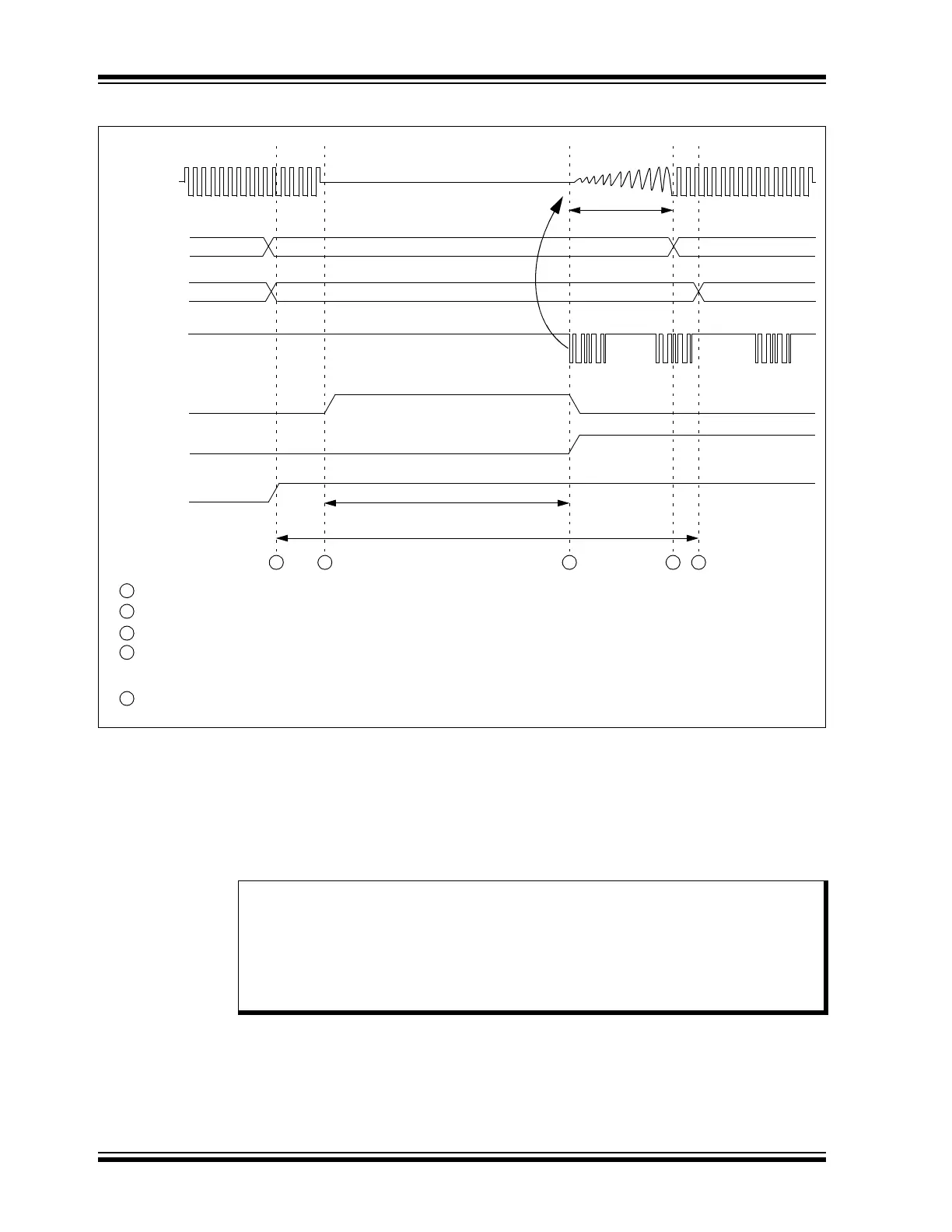
Figure 4-2:
Processor Sleep and CAN Bus Wake-up Interrup
t
The module will monitor the CAN receive line for activity while the module is Sleeping. The
device will generate a wake-up interrupt on the falling edges of CxRX if WAKIE is enabled.
The device will exit Sleep mode after a new mode request or a negative edge on CxRX.
The module will be in Sleep mode if either of the following is true:
• The system is in Sleep mode followed by Disable mode
• The system is in Idle mode with SIDL = 1
T
OST
Processor in
Sleep
2 3 4 5
– Processor executes SLEEP (PWRSAV #0) instruction.
– SOF of message wakes up processor. Oscillator start time begins. CAN message is lost. WAKIF bit is set.
– Processor completes oscillator start time. Processor resumes program or interrupt, based on GIE bits.
accepting CAN bus activity. CAN message is lost.
– Module detects 11 recessive bits. Module will begin to receive messages and transmits any pending messages.
OSC1
CAN B
US
Disabled
001
001000
000 000
000
Sleep
WAKIF
WAKIE
1
– Processor requests and receives Module Disable mode. Wake-up interrupt is enabled.
Processor requests Normal Operating mode. Module waits for 11 recessive bits before
1
2
3
4
5
REQOP<2:0>
OPMOD<2:0>
CAN Module
Note 1: If the module is in Sleep mode, the module generates an interrupt if the WAKIE bit
(C1INTH<14>) is set and bus activity is detected. Due to delays in starting up the
oscillator and CPU, the message activity that caused the wake-up will be lost.
2: The module can be programmed to apply a low-pass filter function to the CAN
receive input line while in Disable, Sleep or Idle mode. This feature can be used to
protect the module from wake-up due to short glitches on the CAN bus lines. The
WAKFIL bit (C1CONL<8>) enables or disables the filter while the module is in Sleep.