2018 Microchip Technology Inc. DS70005340A-page 111
CAN FD Protocol Module
13.0 ERROR HANDLING
Every CAN controller checks the messages on the bus for the following errors: bit, stuff, CRC,
form and ACK errors. Whenever the controller detects an error, an error frame is transmitted
that deletes the message on the bus. Error frames are always signaled using the Nominal Bit
Rate.
Error detection and Fault confinement are described in the ISO11898-1:2015. C1TRECL con-
tains the error counters, TEC and REC (TERRCNTx, RERRCNTx). C1TRECH contains the
error warning and error state bits. TEC and REC increment and decrement according to
ISO11898-1:2015 specifications.
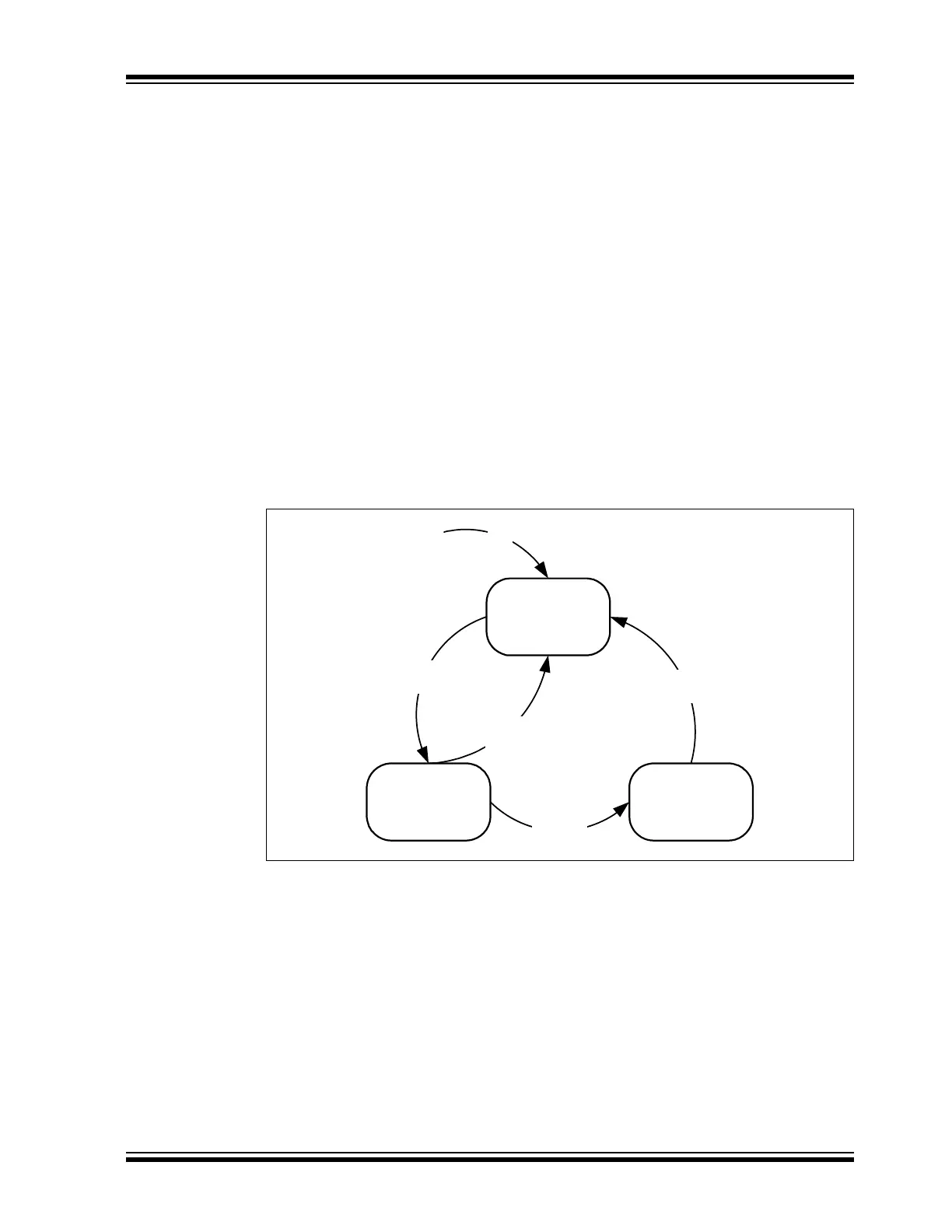
Figure 13-1 illustrates the different error states of the CAN FD Protocol Module. The module
starts in the error active state. If the TEC or REC exceeds 127, the module transitions to the
error passive state. If the TEC exceeds 255, the module will transition to the bus off state.
The module transmits active error frames when in an error active state. It will transmit passive
error frames while in an error passive state. When the module is in bus off, the CxTX pin is
always driven high and no dominant bits are transmitted.
To avoid the module from transitioning to the error passive state, the module will alert the appli-
cation when the TEC or REC reaches 96, using the CERRIF interrupt flag (see Section 12.3.3
“CAN Bus Error Interrupt – CERRIF”). This allows the application to take action before it
enters the error passive state.
Figure 13-1: Error States
The Bus Diagnostic registers provide additional information about the health of the CAN bus:
• C1BDIAG0L and C1BDIAG0H contain separate error counters for receive/transmit and for
Nominal/Data Bit Rates. The counters work differently than the counters in the C1TRECH/L
registers. They are simply incremented by one on every error. They are never
decremented, but can be cleared by writing ‘0’ to the register.
• C1BDIAG1L keeps track of the kind of error that occurred since the last clearing of the
register. The C1BDIAG1H register also contains the error-free message counter. The flags
and the counter are cleared by writing ‘0’ to the register.
The error-free message counter, together with the error counters and error flags, can be used to
determine the quality of the bus.
128 Occurrences
of the Idle Condition
TEC > 255
TEC > 127 or
REC > 127
TEC < 128 and
REC < 128
POR
Error
Active
Error
Passive
Bus Off