dsPIC33/PIC24 Family Reference Manual
DS70005340A-page 88 2018 Microchip Technology Inc.
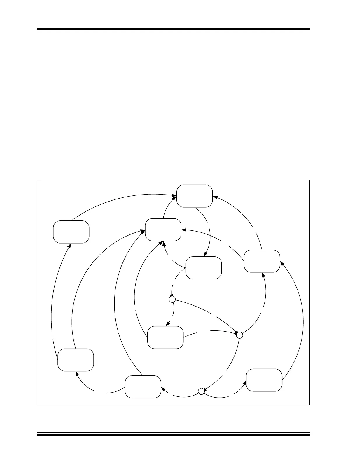
9.2 Receive State Diagram
Figure 9-1 illustrates how messages are received. It illustrates how the most important receive
flags are set and cleared.
• The CAN FD Protocol Module remains Idle until a SOF is detected.
• After a SOF is detected, the module will receive the arbitration and control fields.
• Based on the DNCNTx bits and the received DLC, acceptance filtering will start. See
Figure 8-1 for more details.
• If none of the filters match, the message will still be received, but it will not be stored.
• If a filter matches, the device checks whether the receive object the filter points to is full.
• If the receive object is full, the RXOVIF bit will be set.
• If the receive object is not full, the rest of the data bytes are received and stored to the
receive object.
• If a complete message is received, the message will be stored, a timestamp will be
attached and the receive flags will be set; the FIFO status flags will be updated and the
FIFO head will be incremented.
• In case an error is detected during the reception of a message, an error frame will be
transmitted and the appropriate error flags will be set.
Figure 9-1: Receive State Diagram
Error
Success
Error
Success
Error
Success
Error
Yes
No
Success
Yes
No
Yes
No
Success
Error
SOF
Idle
Receive
Arbitration and
CTRL Field
Transmit Error
Frame
Set Error Flags
c
Filter Match?
Store Message to
Object
Set RXIF
c
Object Full?
RXIF Set?
Set RXOVIF
c
DNCNTx > 0 and DLC > 0?
Receive
Data Bytes 0-3
Receive Remaining
Data Bytes
and Store them
Receive Rest of
Message
Receive Rest of
Message