dsPIC33/PIC24 Family Reference Manual
DS70005340A-page 98 2018 Microchip Technology Inc.
10.4 Transmit Queue Behavior
C1TXQCONL and C1TXQCONH are used to control the TXQ. C1TXQSTA contains the status
flags and the TXQ index (TXQCIx). C1TXQUAL and C1TXQUAH contain the user address of the
next transmit message object to be loaded.
The TXQCI<4:0> bits are used by the CAN FD Protocol Module to calculate the next message
to transmit. TXQCIx bits are not incremented linearly. They are recalculated every time a
message gets transmitted or TXREQ gets set.
Figure 10-15 through Figure 10-20 illustrate how the status flags and user address are updated.
There is no need for the user application to use TXQCIx; therefore, it is not shown in the figures.
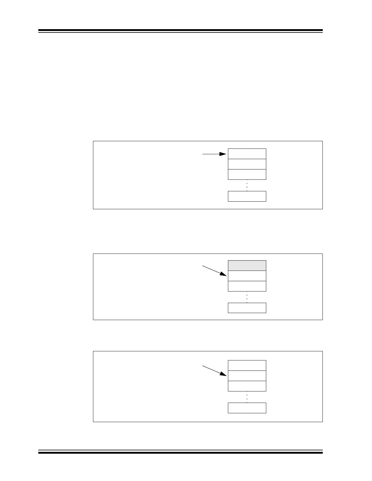
Figure 10-15 shows the status of the TXQ after Reset. Message objects, MO0 to MO7, are
empty. All status flags are set. The user address points to MO0.
Figure 10-15: TXQ – Initial State
Figure 10-16 illustrates the status of the TXQ after the first message (MSG0) is loaded. MO0 now
contains MSG0. The user application sets the UINC bit, which causes the FIFO head to advance.
The user address now points to MO1. TXQEIF is cleared, since the queue is not empty anymore.
The user application now sets TXREQ to request the transmission of MSG0.
Figure 10-16: TXQ – First Message Loaded
Figure 10-17 illustrates the status of the TXQ after MSG0 is transmitted. The TXQ is empty again.
TXQEIF is set and TXREQ is cleared. The user address still points to MO1 because UINC is not set.
Figure 10-17: TXQ – First Message Transmitted
Figure 10-18 illustrates the status of the TXQ after MSG1 is loaded and UINC is set. The user
address now points to the next free message object: MO0.
MO0
MO1
MO2
MO7
C1TXQUAL = 0x090
C1TXQSTA:
TXQEIF = 1
TXQNIF = 1
C1TXQCONL:
TXREQ = 0
MO0/MSG0
MO1
MO2
MO7
C1TXQUAL = 0x0B8
C1TXQSTA:
TXQEIF = 0
TXQNIF = 1
C1TXQCONL:
TXREQ = 1
MO0
MO1
MO2
MO7
C1TXQUAL = 0x0B8
C1TXQSTA:
TXQEIF = 1
TXQNIF = 1
C1TXQCONL:
TXREQ = 0