2010-2013 Microchip Technology Inc. DS30009740B-page 19
Liquid Crystal Display (LCD)
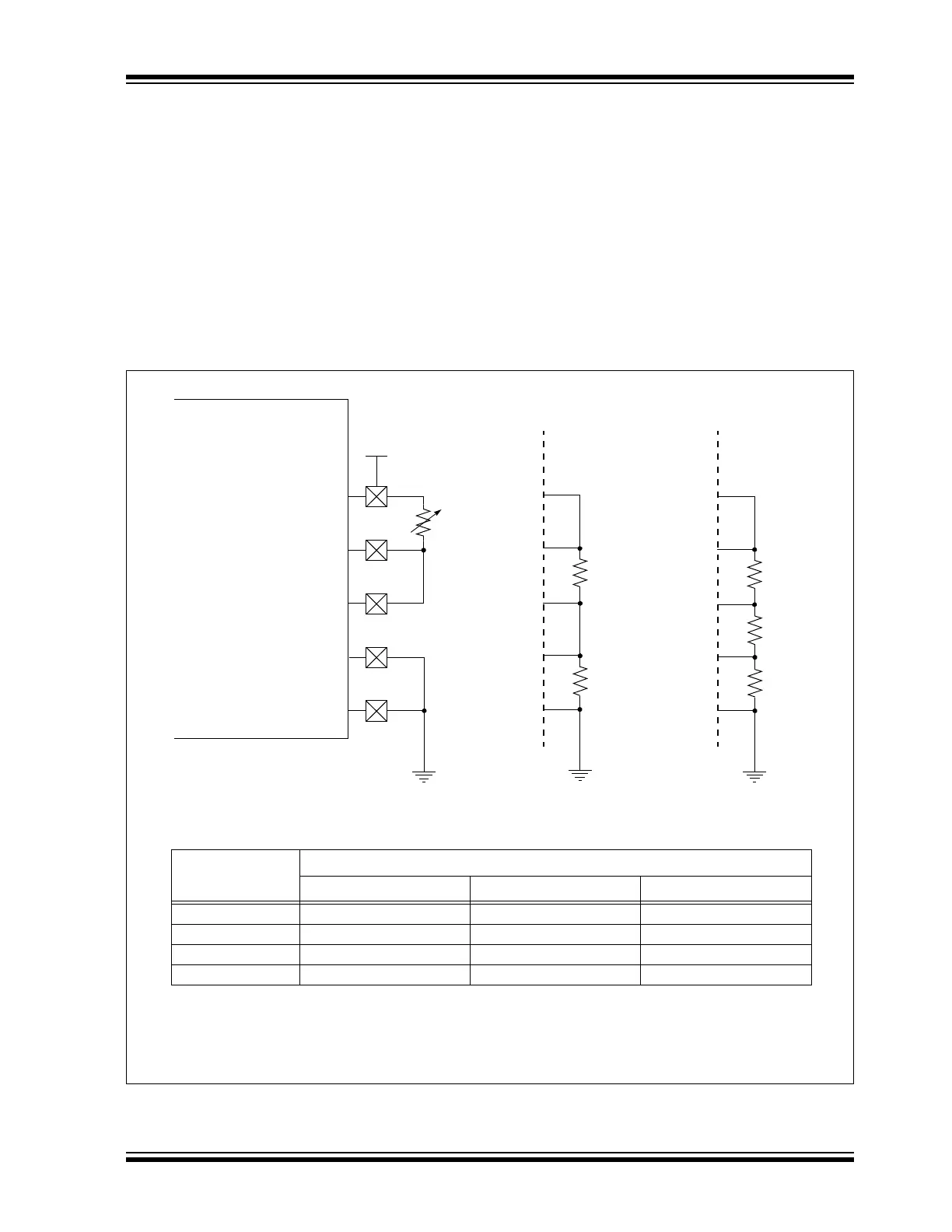
5.3.4 M3 (RESISTOR LADDER WITH HARDWARE CONTRAST)
In M3, the LCD regulator is completely disabled. Like M2, LCD Bias levels are tied to AVDD and
are generated using an external divider. The difference is that the internal voltage reference is
also disabled and the bottom of the ladder is tied to ground (V
SS) (see Figure 5-6). The value of
the resistors, and the difference between V
SS and VDD, determine the contrast range; no soft-
ware adjustment is possible. This configuration is also used where the LCD module’s current
requirements exceed the capacity of the charge pump and software contrast control is not
needed.
Depending on the Bias type required, resistors are connected between some or all of the pins. A
potentiometer can also be connected between LCDBIAS3 and V
DD to allow for hardware
controlled contrast adjustment.
M3 is selected by clearing the CKSEL<1:0> and CPEN bits.
Figure 5-6: Resistor Ladder Connections for M3 Configuration
LCDBIAS3
Note 1: These values are provided for design guidance only. They should be optimized for the application by the
designer based on the actual LCD specifications.
2: A potentiometer for manual contrast adjustment is optional; it may be omitted entirely.
Bias Level at Pin
Bias Type
Static 1/2 Bias 1/3 Bias
LCDBIAS0 AV
SS AVSS AVSS
LCDBIAS1 AVSS 1/2 AVDD 1/3 AVDD
LCDBIAS2 AVDD 1/2 AVDD 2/3 AVDD
LCDBIAS3 AVDD AVDD AVDD
10 k
(1)
10 k
(1)
Static Bias 1/2 Bias 1/3 Bias
LCDBIAS2
LCDBIAS1
LCDBIAS0
AV
DD
10 k
(1)
10 k
(1)
10 k
(1)
VDD
(2)
dsPIC33/PIC24