2016-2023 Microchip Technology Inc. DS50002489G-page 3
RN4870/71
1.0 DEVICE OVERVIEW
1.1 Overview
The RN4870/71 BLE module integrates Bluetooth 5.0
baseband controller, on-board Bluetooth stack, digital
and analog I/Os and RF power amplifier into one
solution.
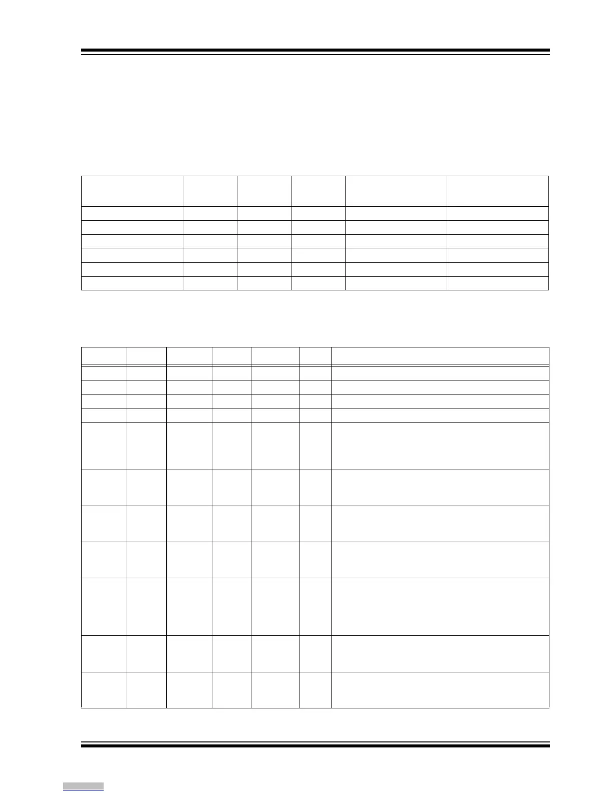
Table 1-1 shows the various options for packaging and
features available in the RN4870/71 family. Table 1-2
provides the description of the pin functions for all the
modules in the RN4870/71 family. Figure 1-1 through
Figure 1-4 show the pinouts for the different modules.
TABLE 1-1: RN4870/71 FAMILY
Part Number
(1)
On-Board
Antenna
Shielding
Number of
Pins
Dimensions
Operating
Temperature Range
RN4870-V/RMXXX Yes Yes 33 12 mm x 22 mm -20°C to +70°C
RN4870U-V/RMXXX No No 30 12 mm x 15 mm -20°C to +70°C
RN4871-V/RMXXX Yes Yes 16 9 mm x 11.5 mm -20°C to +70°C
RN4871U-V/RMXXX No No 17 6 mm x 8 mm -20°C to +70°C
RN4870-I/RMXXX Yes Yes 33 12 mm x 22 mm -40°C to +85°C
RN4871-I/RMXXX Yes Yes 16 9 mm x 11.5 mm -40°C to +85°C
Note 1: The last three digits in P/N indicate the firmware version. At the time of publication, the latest firmware
version is 1.28. Ensure to check the product webpage for the latest part number and firmware version.
TABLE 1-2: PIN DESCRIPTION
RN4870U RN4870 RN4871U RN4871 Name Type Description
— 1 — — GND Power Ground reference.
— 2 — — GND Power Ground reference.
1 3 12 13 GND Power Ground reference.
2 4 11 14 VBAT Power Positive supply input. Range: 1.9V ~ 3.6V.
— — 10 — BK_IN Power Buck power supply input,
Can be connected to the VBAT pin,
Connect to 10 µF low-ESR ceramic capacitor,
Voltage range: 1.9V to 3.6V.
3 5 — — P2_2 D I/O GPIO,
PWM1 (only for RN4870),
Default: Input; pulled high.
4 6 — — VDD_IO Power I/O positive supply. Do not connect.
Ensure VDD_IO and MCU I/O voltage are
compatible.
5 7 — — VDD_IO Power I/O positive supply. Do not connect.
Ensure VDD_IO and MCU I/O voltage are
compatible.
6 8 — — ULPC_O Power 1.2V ULPC LDO output,
Used for diagnostic purposes,
Do not connect to any pin or device,
For measurement, connect a bypass 1 µF
capacitor to ground.
7 9 — — P2_3 D I/O GPIO,
PWM2 (only for RN4870),
Default: Input; pulled high.
8 10 — — BK_O Power 1.55V Buck power supply output for diagnostic
purpose.
Do not connect.
Legend: Pin Type Abbreviations: A = Analog D = Digital I/O = Input/Output I/p = Input O/p = Output
Downloaded from Arrow.com.