2016-2023 Microchip Technology Inc. DS50002489G-page 13
RN4870/71
3.0 INTERFACE PINS
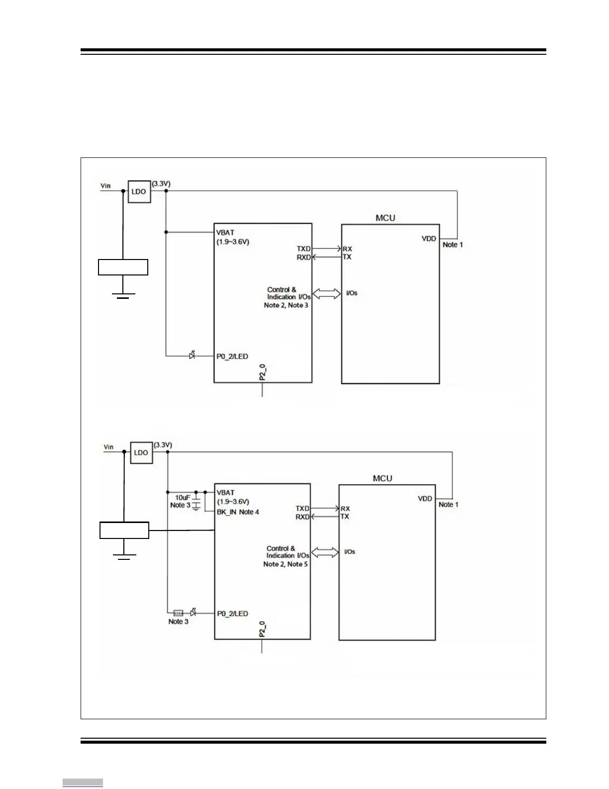
Figure 3-1 shows the power scheme using a 3.3V
low-dropout regulator to the RN487X and a host MCU.
This scheme ensures that the same voltage is used for
both the module and the MCU.
Figure 3-1 also shows the basic UART connections to
the host MCU.
Figure 3-2 shows the recommended connections for
running the RN4870/71 on a coin cell battery.
FIGURE 3-1: POWER SCHEME
System Configurator
System Configurator
System Configurator
System Configurator
Note 1: Ensure VDD_IO and MCU VDD voltages are compatible.
2: Control and Indication ports are configurable.
3: To implement low-power operation, enable the UART_RX_IND
pin and connect to ground.
Note 1: Ensure VDD_IO and MCU V
DD voltages are compatible.
2: Control and Indication ports are configurable.
3: 10 µF (X5R) and 330 Ohm resistor are required for RN487X.
4: BK_IN connects to VBAT for RN4871U.
5: To implement low-power operation, enable the UART_RX_IND
pin and connect to ground.
RN4870/71/70U
RN4871U
Reset
Reset IC
Reset IC
Downloaded from Arrow.com.