2016-2023 Microchip Technology Inc. DS50002489G-page 25
RN4870/71
5.0 APPLICATION REFERENCE
CIRCUITS
5.1 External Configuration and
Programming
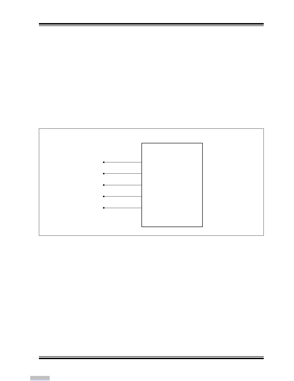
The RN4870/71 module can be configured and firm-
ware programmed using an external configuration and
programming tool. Figure 5-1 shows the mandatory
connections required between the module and the
external programming header. It is recommended to
include these pin connections on the host PCB for
development. For accessing the various configuration
and indication pins, use Ta ble 1-2 , Tab le 1 - 3, Table 1-4
and Tabl e 1 -5.
5.2 Reference Circuit
Figure 5-2 through Figure 5-5 show the reference
circuits for various modules under the RN4870/71 family.
In the circuits, the power input range is 1.9V ~ 3.6V. A
battery reverse protection circuit is recommended in
case a battery power input is used. Note that the
VDD_IO is the same as the power input. In case of an
LED connection, the power input must be greater than
3.0V. For the RN4870U, an RF antenna matching circuit
must also be included, as shown in Figure 5-3.
FIGURE 5-1: EXTERNAL PROGRAMMING HEADER CONFIGURATIONS
RN4870/71
1P2_0 P2_0
VBAT
1RXD
1TXD
1GND
RXD
TXD
GND
1 VBAT
Downloaded from Arrow.com.