2016-2023 Microchip Technology Inc. DS50002489G-page 35
RN4870/71
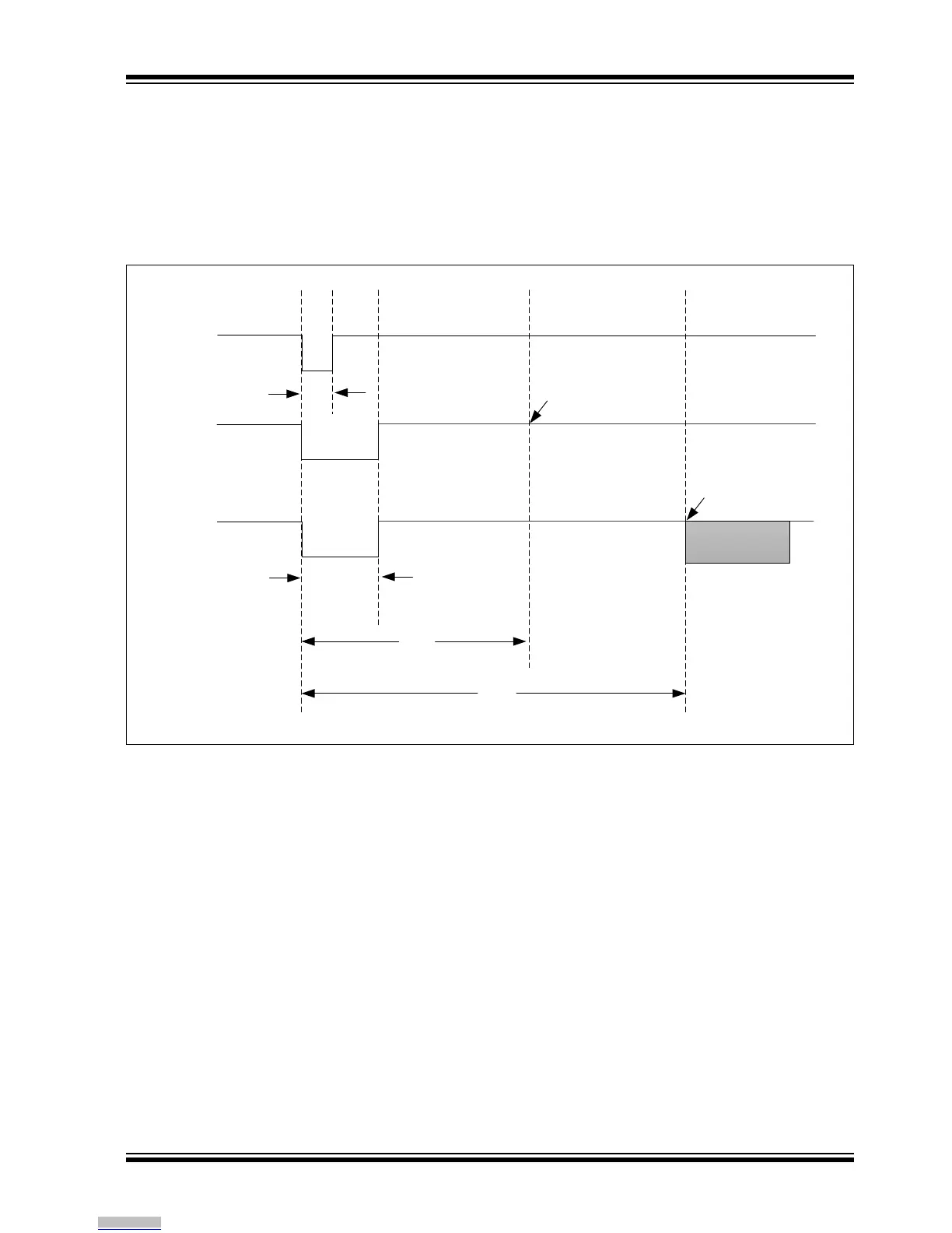
9.0 TIMING CHARACTERISTICS
Figure 9-1 shows the timing diagram for the RN4870/
71 module when it is reset in the Test mode and Appli-
cation mode. Figure 9-2 shows the timing diagram for
the module when it is powered on. In Application mode,
when RN4870/71 is ready to talk to the MCU after
Reset, the module provides a UART response indicat-
ing that the Reset is complete. For more details, refer
to the “RN4870/71 Bluetooth
®
Low Energy Module
User’s Guide” (DS50002466).
FIGURE 9-1: TIMING DIAGRAM OF RN4870/71 UART READY AFTER RESET (IN TEST AND
APPLICATION MODE)
Ext
Reset
1mS
P2_0=0
P2_0=1
25mS
Test Mode
Process
Application
Mode
Process
46mS
68mS
UART Ready
for MCU
UART Ready
for MCU
Status pin/UART
Report Command
Downloaded from Arrow.com.