RN4870/71
DS50002489G-page 36 2016-2023 Microchip Technology Inc.
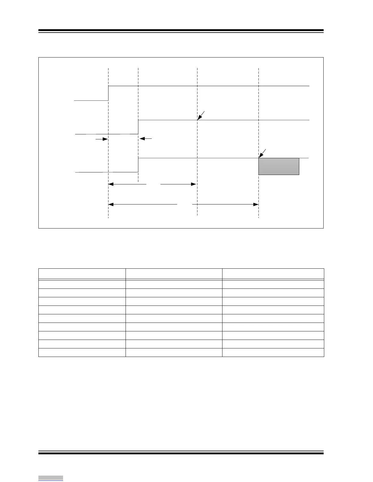
FIGURE 9-2: TIMING DIAGRAM OF RN4870/71 UART WHEN POWERED ON (IN TEST AND
APPLICATION MODE)
The table below shows the error rate for various UART
baud rates for the RN4870/71 module. The system
clock is running at 16 MHz.
VBAT
P2_0=0
P2_0=1
25mS
Test Mode
Process
Application
Mode
Process
46mS
68mS
UART Ready
for MCU
UART Ready
for MCU
Status pin/UART
Report Command
TABLE 9-1: ERROR RATE FOR VARIOUS BAUD RATES ON THE RN4870/71
Set Baud Rate Measured Baud Rate Error
921600 941176 -2.12%
460800 457143 0.79%
307200 307692 -0.16%
230400 231884 -0.64%
115200 115942 -0.64%
57600 57971 -0.64%
38400 38095 0.79%
19200 19048 0.79%
9600 9524 0.79%
Downloaded from Arrow.com.