Copyright 2010 - Microener
2.3 - OPERATION OF THE DIRECTIONAL EARTH FAULT ELEMENT
It is assumed :
Set minimum pick-up residual current : (3Io)
Set minimum residual voltage (3Uo) to enable O> pick-up
Set characteristic angle (max. torque displacement of residual current 3Io from residual
voltage 3Uo).
Actual earth fault relay’s input current
Actual earth fault relay’s input voltage
Displacement of 3Io from 3Uo
Component of 3Io in the direction o
Io = 3Io cos(o-o)
Fig 1 Fig.2
The relay measurement is:
3Io x cos( o -o) = Io
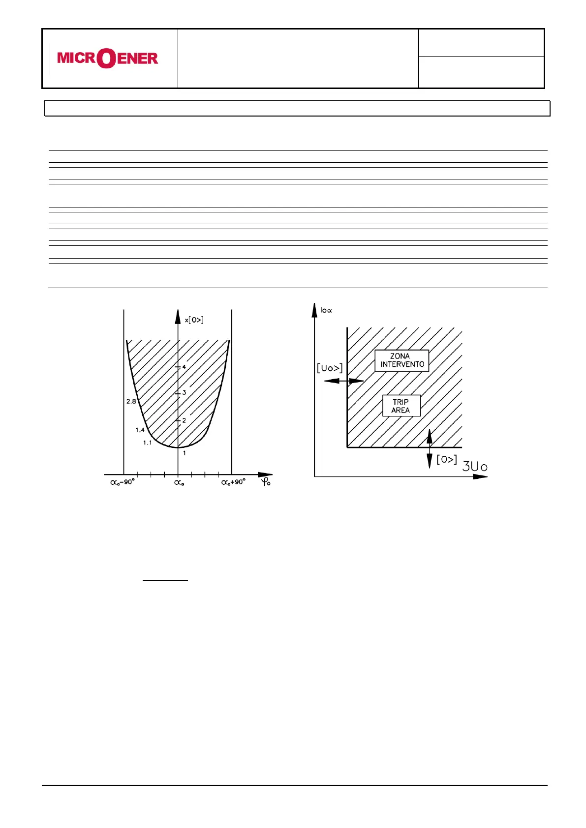
The relay trips when Io>[O>] (fig.2) i.e, when the component of the input current in the measuring
direction of the relay exceeds the set trip level Is. [O>]
Operation is enabled only if the input zero-sequence voltage 3Uo is above the set level [Uo>].
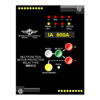
The sensitivity of the relay is then proportional to cos(o -o), it is maximum when o = o
and its operation field is limited within the range:
(o - 90°) < o < ( + 90) (fig.1)
The characteristic angle of the relay must be selected according to the kind of earthing of the installation
which has to be protected against earth fault; typical setting are:
NEUTRAL EARTHED VIA RESISTOR
SOLIDLY EARTHED NEUTRAL