Copyright 2010 - Microener
12.2 - PROGRAMMING THE CONFIGURATION OF OUTPUT RELAYS
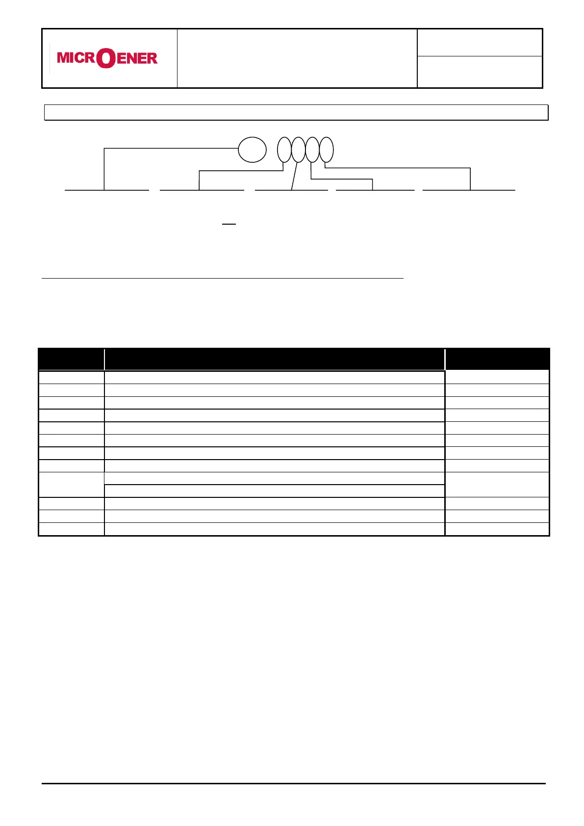
Mode PROG menu FRELAY (Settings out of production are here under shown).
The key "+" operates as cursor; it moves through the digits corresponding to the four relays programmable for any
functions in the sequence 4-3-2-1-L-K-J-I-H-G-F-E-D-C-B-A (4=Relay R4 etc.) and makes start flashing the
information actually present in the digit. The information present in the digit can be either the number/letter of the
relay (if this was already associated to the function actually on programming) or a dot (-) if this place was not yet
addressed.
operates relay R1, R2, R3, R4
Overload prealarm tripping
operates relay R1, R2, R3, R4
Starting switch-over tripping
operates relay R1, R2, R3, R4
Start No limitation tripping
operates relay R1, R2, R3, R4
operates relay R1, R2, R3, R4
Time delayed unbalance tripping
operates relay R1, R2, R3, R4
operates relay R1, R2, R3, R4
Instantaneous overcurrent tripping
operates relay R1, R2, R3, R4
Time delayed overcurrent tripping
operates relay R1, R2, R3, R4
Instantaneous earth fault tripping
operates relay R1, R2, R3, R4
Time delayed earth fault tripping
operates relay R1, R2, R3, R4
Remote trip command (input 1-2)
operates relay R1, R2, R3, R4
Time delayed Phase loss tripping
operates relay R1, R2, R3, R4
This dash means
that output relay
number 1 is not
assigned to this
element
This is the name of
protective element
The number 2
means that
output relay 2 will
operate when
this element trips
This dash means
that output relay
number 3 is not
assigned to this
element
The number 4 means
that output relay 4 will
operate when this
element trips