MANUAL.LM20 Revision C January 2023 Page 11 of 52
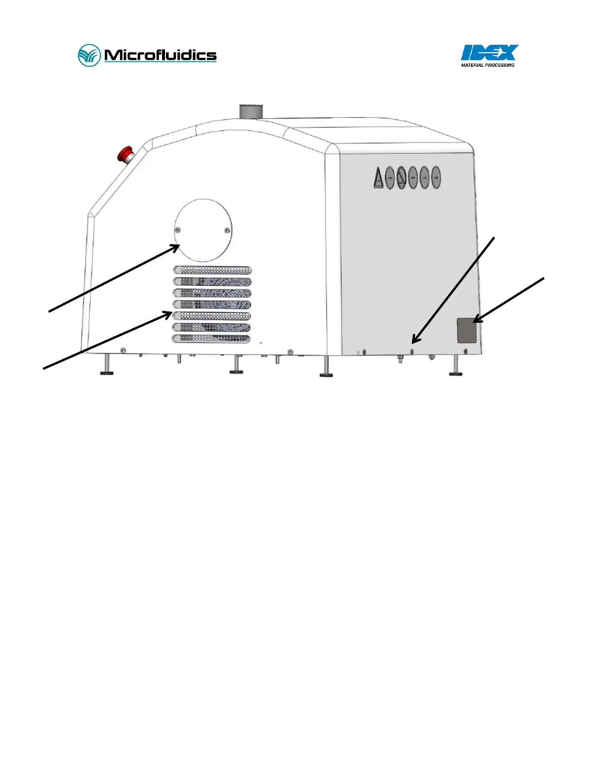
Figure 1 – LM20 Overview Diagram – shown with optional accessories
Standard Features (shown in Figure 1):
1. Machine Name Plate: Details model information and serial number.
2. Cover Fasteners: Secures the cover to the base plate.
3. Air Ventilation Inlet: Air inlet for the hydraulic cooling system. Do not obstruct air path, or system
damage will occur.
4. Access Cover for Accumulator: Removing this cover will provide access to the hydraulic accumulator.
5. Power Disconnect: Lockable electrical power disconnect switch.
6. Power Cord: 10 feet (3m) cable. Customer responsible for wiring into power supply.
7. Air Ventilation Outlet: Air outlet for the hydraulic cooling system. Do not obstruct the air path or
system damage will occur.
8. Emergency Stop: Emergency Stop button. Push to stop, twist to reset.
9. Touch Screen Interface: Human machine interface (HMI). Used to control machine functions, set
pressure, turn intensifier and motor on/off.
10. Interaction Chamber: location of the geometrically fixed micro channels.
11. Intensifier Pump Head: Location of pressure intensification.
12. Access Cover for Oil Reservoir: Removing this cover will provide access to the hydraulic oil reservoir.
13. Inlet Reservoir: Glass reservoir (standard). Fill with preprocessed material.
14. Product Outlet: Post-processed material exits the system.