© Microhard 30
3.0 Hardware Features
Pin Name No. Description Dir
RX_N4 41
Ethernet Port 4 (WAN) Receive Pair
RX_P4 42
TX_N4 43
Ethernet Port 4 (WAN) Transmit Pair
TX_P4 44
ETH4 LINK_LED 49 Active high output indicates Ethernet port 4 link status. Active high, cannot drive
LED directly. Requires current limiting resistor. 8mA maximum.
O
TX_P0 55
Ethernet Port 0 (LAN) Transmit Pair
TX_N0 56
RX_N0 57
Ethernet Port 0 (LAN) Receive Pair
RX_P0 58
ETH0 LINK_LED 60 Active high output indicates Ethernet port 0 link status. Active high, cannot drive
LED directly. Requires current limiting resistor. 8mA maximum.
O
Vdd 61,62 Positive voltage supply voltage for the digital section of the module (3.3V). I
Vpa 63,64 Positive voltage supply voltage for the radio module (3.3-5V). I
Table 3-3: pMDDL Pin Description (continued)
All serial communications signals are logic level (0 and 3.3V). DO NOT connect RS-232 level (+12, -
12VDC) signals to these lines without shifting the signals to logic levels.
See Appendix D: Sample Interface Schematic for a sample schematic that can be used to interface to
the pMDDL OEM module.
3.1.9 USB Device Mode
The pMDDL can be set to operate as a USB Device. When set as a USB device, Microhard Composite
Drivers can be installed on a USB Host to provide Ethernet and Serial functionality to the USB port on the
pMDDL. To enable USB Device mode, Pin 14 must be connect to GND through a 1K resistor as shown
below:
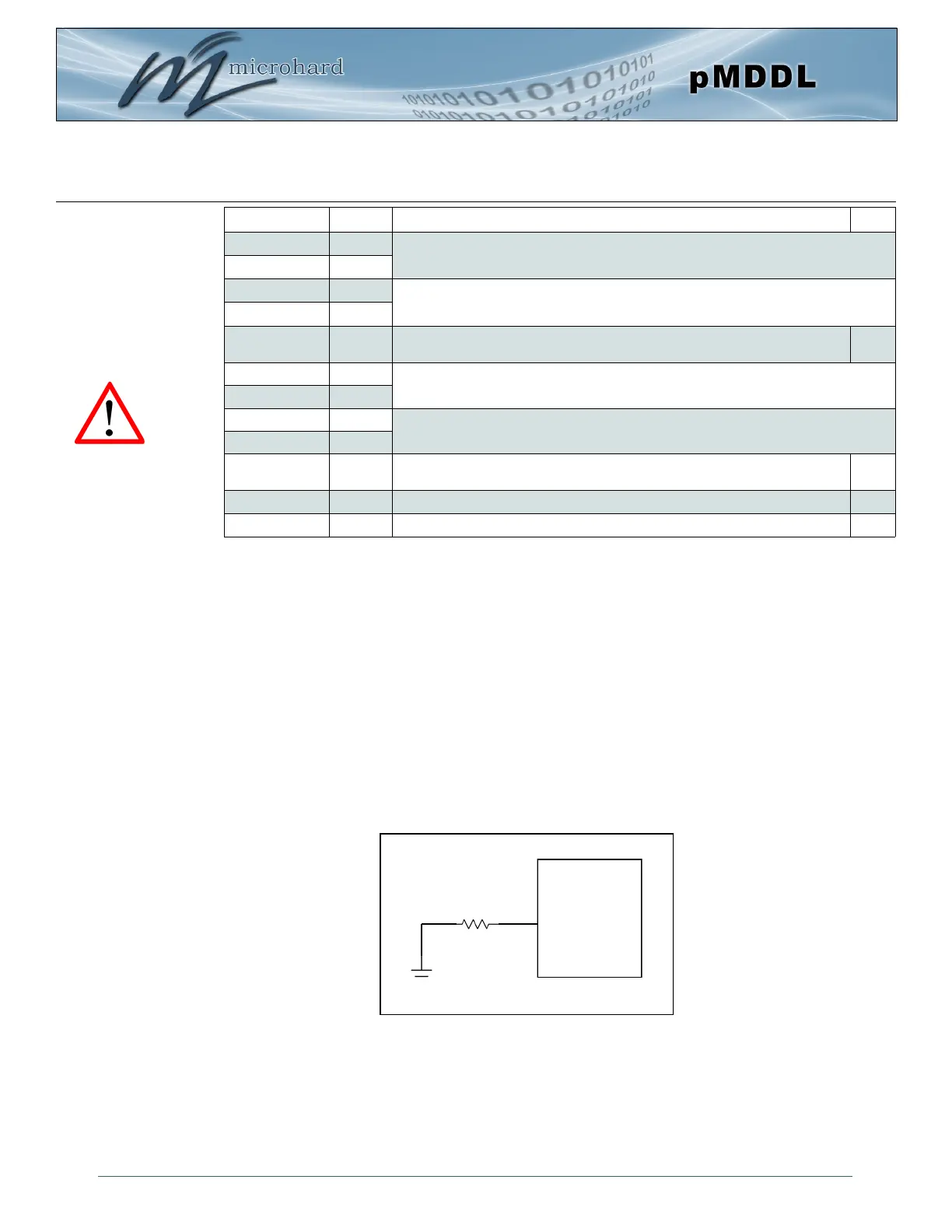
Caution: During power up
or reset, output pins from
the Pico are in an unknown
state. It is advised to use
pull up or pull down
resisters as appropriate.
Drawing 3-6: pMDDL USB Device Mode
pMDDL
GND
1 kΩ
14
USB Mode