DOC 6501_Release V
ATS-6501 Users Guide
38
antenna delay value has been properly set use the save command to save the current delay to
ensure the system uses the correct delay value after a reboot or power cycle. Users can verify the
value was set properly by using the settings gps:antenna_delay command and reviewing the
settings.
Note: The new delay value will take effect immediately and could cause an alarm if the delay
value forces the UTC(UNSO) offset to be larger than 100 ns. The system will steer the internal
clock to remove the antenna delay, if the alarm light came on it will go out once the UTC Value is
within 100 ns. The ATS-6501 outputs will now be accurate to the coarse calibration accuracy
specified in Appendix A.
ATS-6501>antenna_delay 1.185E-7
[OK] 2013-08-05T16:43:29Z
ATS-6501>settings gps:antenna_delay
1.185000000000000e-07
[OK] 2013-08-05T16:55:38Z
2.6 On Time Point (OTP)
The OTP of a system is defined as the point at which the timing signals coincide with
UTC(USNO). Typical systems use distribution amplifiers and cabling to distribute timing signals
from a single source to multiple users. This distribution network will delay the timing signals and
affect their accuracy. For this reason it is important to select an appropriate OTP so that the
desired timing signals are accurate when they reach the user.
This section describes calibration of the ATS-6501 assuming that the OTP of the system is the
rear panel of the ATS-6501. This is not generally a convenient location for the OTP of the
system because there will be a delay associated with the distribution of the signals to the user.
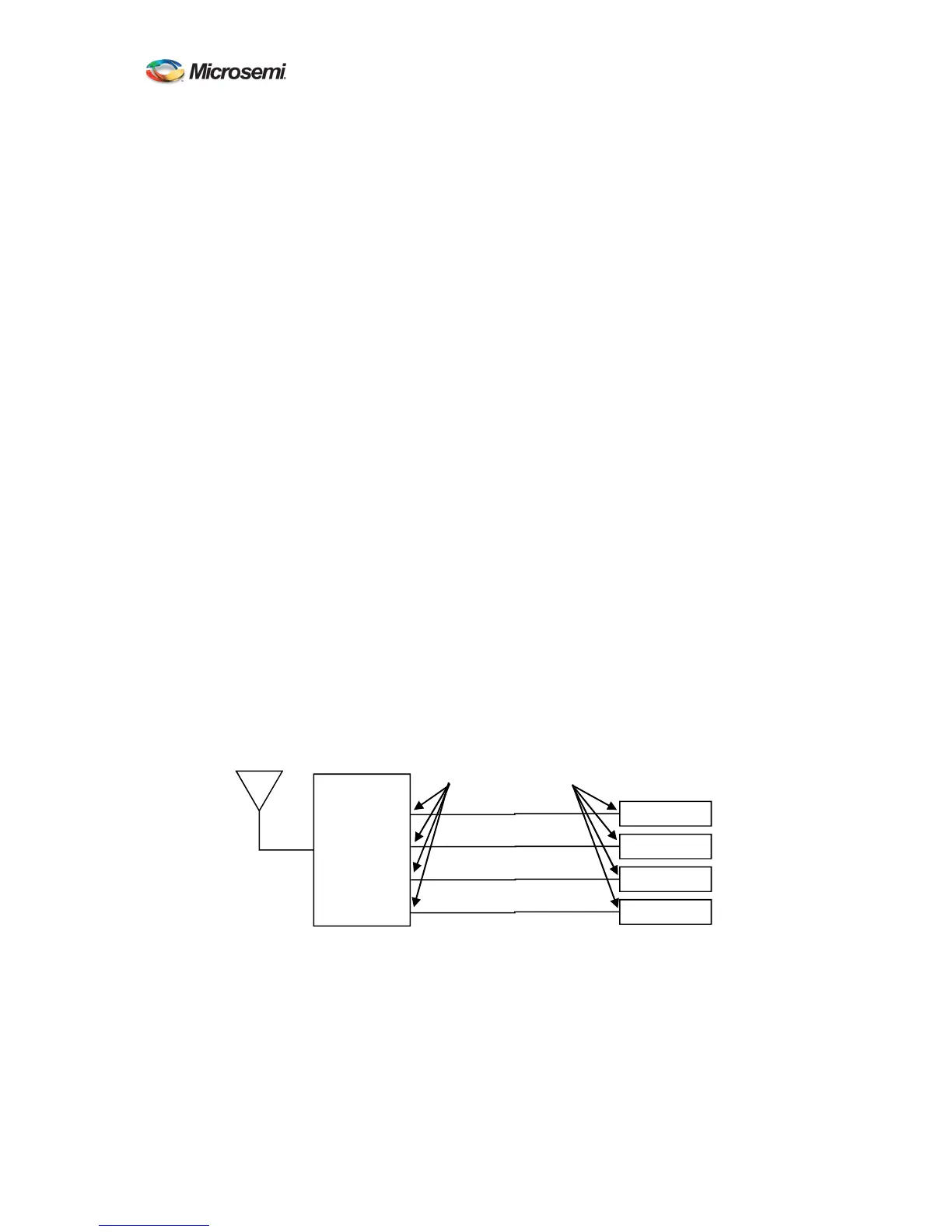
Figure 5 illustrates how to move the OTP of the system from the rear panel of the ATS-6501 to
the user inputs. In moving the OTP of the system it is imperative that the distribution delays from
the ATS-6501 to each of the users is equal. This will ensure that all users receive accurate timing
signals.
Once the delay of the distribution network is known the OTP of the system can be shifted from
the output of the ATS-6501 to the input of user equipment. Equation 2-4 is used to calculate the
antenna_delay value that should be entered into the system to adjust the OTP. The
Distribution_Delay is the measured delay of the timing distribution network as shown in Figure
5. The ATS_6501_Delay is the delay calculated in Equation 2-2 or the calibrated delay given by
Microsemi.
ATS 6501
User 1
User 2
User 3
User 4
PPS Output 1
PPS Output 2
PPS Output 3
PPS Output 4
OLD OTP
NEW OTP
Delay 1
Delay 2
Delay 3
Delay 4
Delay 1 = Delay 2 = Delay 3 = Delay 4 =
Distribution_Delay