Hardware Components
UG0048 User Guide Revision 5.1 5
3.3 PLL Parts and Usage on ProASIC3/E
This section describes the PLL parts and usage on ProASIC3/E.
3.3.1 Instructions for PLL Activation on Board
In order to use the PLLs on the ProASIC3/E Starter Kit board, power must be applied to their respective
analog supply rails. For the west side PLL, known as PLF, the VCCPLF line must be connected to VCC,
which is held at 1.5 V. The same is true for VCCPLC of the PLL on the east side, known as PLC. In
addition, the VCOMPLF and VCOMPLC lines must be connected to ground. The jumpers JP49 and JP50
are provided on the starter kit to connect VCCPLF and VCCPLC pins to 1.5 V supply.
The ground pins of the PLL supplies are connected to ground on the board. These supply voltages are
not connected by default on the board for three reasons:
1. The PLC analog voltage rails are not available on ProASIC3 devices; only on ProASIC3E in the
PQ208 package. Only the west side PLL, namely PLF, is available on ProASIC3 devices in PQ208.
In ProASIC3 devices, the pins are used as general I/Os. The same board is used for ProASIC3E
and ProASIC3 devices.
2. To demonstrate the lowest possible power consumption for the part. Perpetually powering the PLL
lines would not achieve that.
3. It is easy to place a jumper on the appropriate jumper header when desired.
3.4 Power Supply
A 9 V power supply is provided with the kit, as shown in the following figure. There are many power
supply components in the starter kit board to illustrate the many ways that differing voltage banks may be
supported with ProASIC3 and ProASIC3E technology. These voltage banks are not required for general
usage of ProASIC3 silicon. They are provided purely for illustrative purposes.
Note: The latest revision of ProASIC3/E Starter Kit (A3PE-STARTER-KIT-2) does not has an OLED populated
on the board.
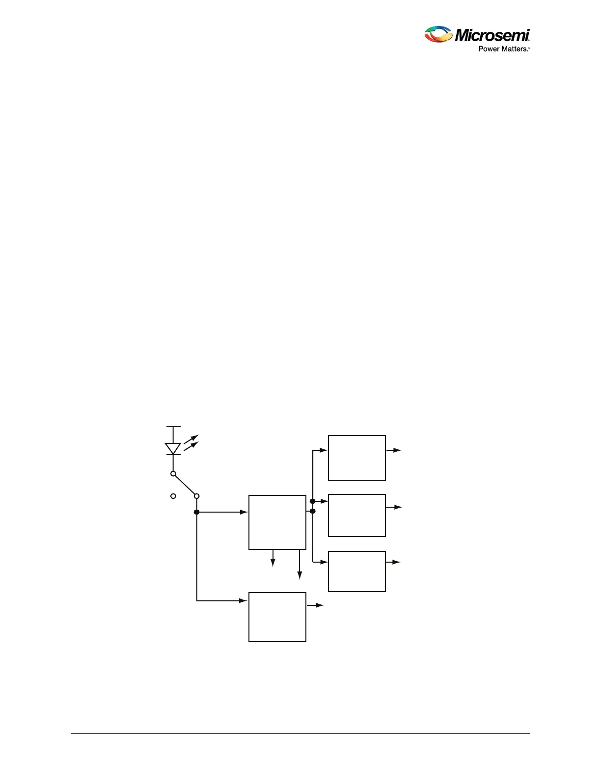
Figure 2 • Power Supply Block Diagram
To use the ProASIC3/E Starter Kit board with a wall mount power supply, use the switching brick power
supply that is provided with the kit.
The external +9 V positive center power supply provided to the board through connector J18 goes to a
voltage regulator chip U11 on the Starter Kit board. As soon as the external voltage is connected to the
On
Red
O
+9 V DC Supply
2 A Max
D19
3.3 V
Regulator
V
PUMP
10 V Step-up
DC/DC
converter
1.5 V
Regulator
1.8 V
Regulator
2.5 V
Regulator
Core FPGA
Vol tag e
OLED10 V Supply
SW11
OLED 3.3V supply