Description of Test Design
UG0048 User Guide Revision 5.1 16
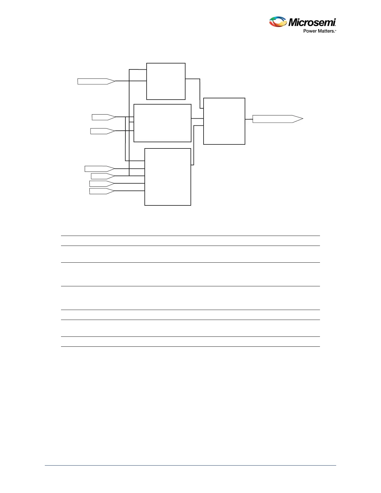
The following figure shows a block diagram of the Data_Block.
Figure 4 • Data Block Diagram
The following table lists the functionality of different switches.
Table 8 • Switches
Action Results
Press SW2 Up-Down control for the 8-bit counter. Press and hold SW2
for down count.
Press SW3 Synchronous load for the 8-bit counter. Press SW3 for
loading from the hex switches. Holding the SW3 displays
the hex switches value on LEDs.
Press SW4 Direction control for LEDs flashing. While LEDs flashing is
selected with SW6, SW4 can be used to change the LEDs
flashing direction.
Press SW5 Asynchronous clear for the whole design.
Press SW6 Select for DATA_BLOCK. It allows switching LED output
between the counter and flashing data.
Change Hex Switch setting (U13 and U14) Changes the loaded data for the eight-bit counter.
Clock
Ac lr
count8_instance
mux2A[7:0]
A[7:0]
B[7:0]
Y[7:0]
S
DATA_MUX
DATA_LED[7:0]
SW6_MuxSel
Data_select
Clock
Updown
Ac lr
Sload
Ac lr
CLK
Q
LED_Flashing
Q[7:0]
LED_Flashing_instance
count8
Clock
Updown
Ac lr
Sload
HexAB[7:0]
Direction
Direction
HexAB[7:0]
Data [7:0]