Hardware Components
UG0048 User Guide Revision 5.1 3
3 Hardware Components
This section describes the hardware components of the ProASIC3/E Starter Kit board.
3.1 ProASIC3/E Starter Kit Board
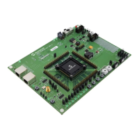
Figure 1, page 4 illustrates a top-level view of the ProASIC3/E Starter Kit board.
The ProASIC3/E Starter Kit board consists of the following:
• Wall mount power supply connector, with a switch and a LED indicator
• Switches to select from among 1.5 V, 1.8 V, 2.5 V, and 3.3 V — I/O voltages on banks 4 and 5
(southern side)
• 10-pin 0.1 inch pitch programming connector compatible with Altera connections
• 40 MHz oscillator and two independent manual clock options for global reset and pulse
• Eight LEDs (driven by outputs from the device)
• Jumpers (allow disconnection of all external circuitry from the FPGA)
• Two mono stable pulse generator switches (global and reset)
• Four switches (provide input to the device)
• Two hex switches to provide four inputs each to the FPGA, and which are set to a user-switchable
hexadecimal input value
For more information, see Appendix: PQ208 Package Connections, page 22 and Appendix: Board
Schematics, page 26.