EasyManua.ls Logo

Microsoft Surface Laptop Go - User Manual

Microsoft Surface Laptop Go
19 pages
Print Icon
To Next Page IconTo Next Page
Loading...
Surface Laptop Go
SSD Removal Procedure
M1171431
SP
Question and Answer IconNeed help?

Do you have a question about the Microsoft Surface Laptop Go and is the answer not in the manual?

Summary

Device Identity Information

Surface Laptop Models

Identifies specific Surface Laptop Go models.

General Information, Precautions, Warnings

Tools and Jigs

Lists essential tools and diagnostic software for device servicing.

General Safety Precautions

Outlines general safety measures to prevent injury during device handling.

Specific Precautions and Warnings

Details specific safety warnings and precautions to follow before and during disassembly.

Safety Policies;Procedures

Provides guidance on reporting and managing safety-related device issues.

Diagnostics;Troubleshooting Overview

Software Tools

Lists available software tools for system diagnostics and updates.

Verify Hardware Functionality

Describes the process for verifying hardware functionality using diagnostic tools.

SSD Removal and Reassembly Procedures

Prior to Device Disassembly

Essential pre-disassembly steps including power off and ESD safety.

Current Battery Warning

Critical warnings regarding battery safety and user replacement limitations.

SSD Removal Process

Preliminary Requirements

Outlines key requirements and cautions before starting the SSD removal procedure.

Required Tools and Components

Lists all necessary tools, components, and software for SSD removal.

Prerequisite Steps

Details crucial steps like powering off and positioning the device before disassembly.

Process Steps: Feet removal and C-cover screws

Steps for removing device feet and C-cover screws using specific tools.

Process Step: Separate C-cover from device

Procedure for separating the C-cover by unsnapping hook and snap features.

Process Steps: Position C-cover and Disconnect FPCs

Steps to position the C-cover and disconnect Flexible Printed Circuits from the main board.

Process Steps: Remove SSD Shielding, Clean TIM, and Remove SSD

Instructions for removing SSD shielding, cleaning TIM residue, and extracting the SSD.

Reinstall C-cover Keyboard Process

Check for items and Connect C-cover FPC

Steps to check device for foreign objects and reconnect the C-cover FPC.

Connect Battery FPC and Align C-cover

Connects the battery FPC and aligns the C-cover correctly before closing.

Install C-cover Screws

Secures the C-cover by installing the previously removed screws.

Environmental Compliance Requirements

Overview

This document outlines the procedures for the SSD removal and reassembly of the Microsoft Surface Laptop Go, model 1943. It is intended for technicians and users who need to perform maintenance or troubleshooting on the device. The manual emphasizes safety precautions, proper tool usage, and environmental compliance throughout the process.

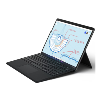
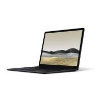
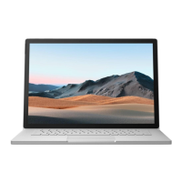
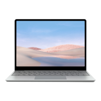
The Surface Laptop Go is a portable computing device designed for everyday use, offering a balance of performance and portability. Its design incorporates a keyboard trackpad assembly (C-cover) and a bottom case (D-bucket or chassis), with internal components such as the Solid-State Drive (SSD) housed within. The device is designed with specific assembly and disassembly procedures to ensure its integrity and functionality.

Function Description

The Surface Laptop Go functions as a personal computer, providing capabilities for productivity, communication, and entertainment. It integrates a display, keyboard, and trackpad for user interaction, powered by an internal battery and capable of external power supply. The SSD serves as the primary storage component, housing the operating system, applications, and user data. The device's architecture allows for the SSD to be accessed for specific maintenance procedures, although the manual explicitly states that SSD re-installation or replacement should not be attempted by users due to potential damage and safety concerns, and such actions would void the warranty.

Usage Features

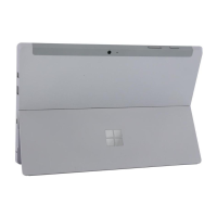
The Surface Laptop Go is designed for ease of use with its integrated keyboard and trackpad. The device's model and serial number are conveniently located on the bottom center, closest to the display hinge point, for easy identification. The manual references several Microsoft-provided software tools to enhance the user experience and facilitate maintenance, including:

  • How To: Update Surface device firmware and OS: Ensures the device runs on the latest software for optimal performance and security.
  • Download: Surface drivers and firmware: Provides necessary drivers for hardware components to function correctly.
  • Download: Surface Diagnostic Toolkit (SDT): A crucial tool for diagnosing hardware failures and verifying device functionality. It guides users through updating the device to the latest OS/FW versions and running diagnostics to identify persistent issues.
  • Download: Surface Data Eraser: A utility for securely erasing data from the SSD, important for privacy and data security before device disposition.
  • Download: Surface Imaging Tools: For managing device images, potentially for system recovery or deployment.

These tools collectively support the device's operational integrity and provide users with resources for self-service troubleshooting and maintenance, within the scope of recommended procedures.

Maintenance Features

The manual details a specific maintenance procedure: the SSD removal process. This process is outlined with clear, step-by-step instructions and emphasizes safety and precision.

Prior to Device Disassembly:

  • Power Off and Disconnect: The device must be powered off and disconnected from any power supply to prevent electrical hazards.
  • ESD-Safe Environment: Work surfaces must be covered with ESD-safe, soft, non-marring material and regularly cleaned to prevent debris or abrasive particles from damaging the device. An anti-static wrist strap (1 MOhm resistance) and ESD-safe benchtop are required to prevent electrostatic discharge.
  • Battery Safety: A critical warning is provided regarding the internal battery. An ESD-safe battery cover is recommended to be placed across the device to protect the battery from physical contact or accidental damage whenever the C-cover is removed. The battery FPC (Flexible Printed Circuit) must remain disconnected from the PCBA (Printed Circuit Board Assembly) for safety. The battery itself is not user-replaceable, and any damage to it (leaking, expansion, folds) during the process requires immediate cessation of activities and direct contact with Microsoft.

Tools and Jigs:

The procedure requires a specific set of tools, including:

  • Microsoft Recommended Jigs: ESD-safe battery cover.
  • Standard Tools: Anti-static wrist strap, ESD-safe benchtop, spudger tool, plastic opening pick, plastic opening tool, Phillips drivers (PH0, PH00), Isopropyl alcohol dispenser bottle (70% IPA), cleaning swabs, ESD-safe tweezers, and lint-free cleaning cloths. These tools are readily available from various commercial vendors.

Process Steps for SSD Removal:

  1. Feet Removal: Non-skid foot pads (feet) are carefully lifted and removed using plastic tweezers or a spudger. All adhesive residue must be cleaned with 70% IPA.
  2. C-cover Screws Removal: Seven screws (three from the rear, four from the front foot recesses) securing the C-cover are uninstalled using a PH0 screwdriver. Caution is advised to ensure all screws are removed to prevent damage during C-cover removal.
  3. Separate C-cover from Device: A plastic opening tool is used to slowly pry the C-cover upwards, disengaging hook and snap features. The process involves prying from the front, then left and right sides, and finally tilting the device backward while pressing the C-cover towards the display to unsnap remaining hooks. Extreme caution is necessary to avoid damaging internal features, the Flexible Printed Circuit (FPC) connecting the C-cover to the main board, and the display glass. The C-cover should not be pulled apart beyond 45 degrees.
  4. Position C-cover for FPC Removal: After lifting, the C-cover is angled and hovered with the far side facing down towards the device, making the C-cover FPC accessible.
  5. Disconnect FPCs: While hovering the C-cover, both the battery FPC and the C-cover FPC are disconnected from the main board using a spudger to pull up locking tabs and slide the FPCs out. The C-cover should then be placed in a safe location, key and trackpad side down, with the FPC facing up to prevent bending or creasing.
  6. Remove SSD Shielding Cover and Screw: A plastic opening tool is used to pry up the SSD shielding cover, and a PH00 screwdriver removes the screw securing the SSD.
  7. Clean TIM Residue: The SSD is inspected for Thermal Interface Material (TIM) residue, which is carefully wiped away with 70% IPA.
  8. Remove SSD: The SSD is carefully gripped by its sides and pulled out of the mainboard socket at approximately a 15-degree angle.

Reinstall C-cover Keyboard Process:

  1. Check for Unexpected Items: Before reassembly, both the C-cover and device enclosure are thoroughly inspected for any loose articles or foreign objects, especially around the battery area.
  2. Connect C-cover FPC: The C-cover is hovered over the device, and the C-cover FPC is slid into its connector on the main board, then the locking tab is pressed down. Caution is given to ensure the FPC bends fall into place properly without folds or creases.
  3. Connect Battery FPC: The battery FPC is connected to the main board in the same manner.
  4. Align the C-cover: The C-cover is carefully aligned with the unit using front edge alignment posts, placed back onto the D-bucket, and gently pressed to engage the snaps. Verification is required to ensure no visible gaps remain between the C-cover and D-bucket. A warning emphasizes correct alignment to prevent display damage when closing the device lid.
  5. Install C-cover Screws: The unit is closed and turned over. The previously removed C-cover screws are installed using a PH0 screwdriver. Two longer screws are specifically designated for the rear corner locations under the foot pad. All screws should be snug, then turned an additional 90 degrees (1/4 turn).

Environmental Compliance Requirements:

The manual concludes with a section on environmental compliance, stating that all waste electrical and electronic equipment (WEEE), components, batteries, and residuals must be managed according to applicable laws, regulations, and specific conformance standards (H09117). A link to Microsoft's download page for these standards and a contact email for questions are provided.

Overall, the manual serves as a comprehensive guide for the safe and correct SSD removal procedure for the Surface Laptop Go, emphasizing user safety, device integrity, and adherence to environmental guidelines. It clearly delineates between user-performable tasks and those that require professional intervention or are explicitly discouraged due to warranty implications and potential damage.

Microsoft Surface Laptop Go Specifications

General IconGeneral
Display Size12.4 inches
Processor10th Gen Intel Core i5-1035G1
RAM4GB or 8GB LPDDR4x
GraphicsIntel UHD Graphics
Operating SystemWindows 10 Home in S mode
Battery LifeUp to 13 hours
Ports1 x USB-C, 1 x USB-A, 3.5 mm headphone jack, 1 x Surface Connect port
Camera720p HD f2.0 front-facing camera
AudioOmnisonic Speakers with Dolby Audio
Color OptionsPlatinum, Ice Blue, Sandstone
Resolution1536 x 1024
Storage64GB eMMC, 128GB SSD, or 256GB SSD
Weight2.45 pounds (1.11 kg)
WirelessWi-Fi 6 (802.11ax), Bluetooth 5.0

Related product manuals