3. INSTALLATION
3.1 AC Line Connections
The unit is provided with a power cable capable of carrying the input current for both 115V and
230V operation. This cable should be connected via a suitable connector to the local AC power
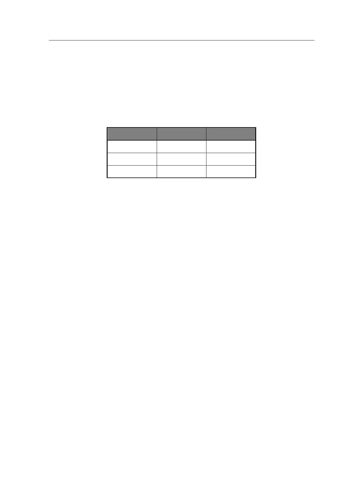
supply. The colour code employed is as follows:
The supply voltage setting can be checked by looking through the transparent window on the
rear panel next to the power inlet socket. This can be changed by first disconnecting the unit
from the electrical supply, removing the window and adjusting the switch to read the required
voltage. Replace the window and ensure that the fuse rating is correct:
No adjustment is required for variation of supply frequency.
Before connecting the AC power, read the precautions listed under section 1.2—AC Power
Supply.
The instrument is not suitable for battery operation.
The power switch is located on the left of the front panel.
3.2 Measurement Connections
The 6375 Series can be used with any of the following Microtest leads, fixtures or adaptors.
Kelvin Clip Leads (Fine Jaws), Part No. 1EVA40100
General purpose 4-terminal measuring leads for conventional components giving good accuracy
except for measurement of very small capacitances or very small inductances where the use of
the 4-terminal component fixture, part number 1EV1006, will give more accurate results.
Kelvin Clip Leads ((large jaws), Part No. 1EVA40180
Similar to part number 1EVA40100 but with larger jaws making them more suitable for
connection to terminal posts or larger diameter component leads.