Do you have a question about the Microtest 6375 and is the answer not in the manual?
Safety requirements for electrical equipment for measurement, control & laboratory use.
Guidelines for connecting the instrument to the AC power supply, including cable and plug requirements.
Safety precautions when performing adjustments, maintenance, or repairs on the equipment.
Precautions to avoid damage from static electrical discharge when handling components.
Details on connecting the unit to the local AC power supply, including voltage setting and fuse.
Describes various Microtest leads, fixtures, and adaptors for measurement connections.
Identifies and explains the connectors and controls located on the rear panel of the instrument.
Details the specific connectors on the rear panel and their uses.
Describes the DC 5V output and external trigger input on the rear panel.
Explains the GPIB port for communication and remote control of the instrument.
Instructions for powering on the instrument and adjusting display contrast.
Guidance on the proper procedure for powering off the instrument.
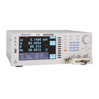
Details the layout and function of the front panel controls and display elements.
Explains the function of soft keys, which change based on the selected mode.
Describes the use of navigation keys for selecting parameters and adjusting values.
Details the function of dedicated control keys like Bias, Local, Menu, and Trigger.
Explains the multi-function data entry keypad for manual input of values and codes.
Explains the purpose and process of trimming to eliminate stray capacitance or series impedance.
Guides the user through performing open-circuit or short-circuit trims for accurate measurements.
Provides instructions and an example for measuring a component using the instrument.
Illustrates the process of measuring capacitance and dissipation factor of a 470nF capacitor.
Details the parameters selectable in the MEASUREMENT MODE via soft keys.
Explains the use of BNC sockets for screened cable connections to the device under test.
Discusses best practices for accurate measurement of small value capacitors.
Details accurate measurement of low inductance values, recommending specific fixtures.
Addresses the effective value variation of inductors with magnetization and test signal levels.
Allows component measurement at user-defined steps with different parameters for each step.
Explains how to access and modify parameters like line frequency, beep, and GPIB address.
Covers GPIB protocol, interface specifications, and control mechanisms for instrument communication.
Lists and summarizes SCPI commands specific to the 6375 series instrument.
Provides example programs for controlling the instrument via GPIB.
Details the parameters that can be measured and displayed by the instrument.
Specifies the test conditions, including AC drive parameters like frequency range.
Describes the four selectable measurement speeds and their impact on resolution and noise.
Outlines the display ranges for different measurement parameters like R, Z, X, L, C, etc.
Explains the available operating modes, including MEASUREMENT and MULTI-STEP.
Describes the front panel BNC connectors and terminal capabilities for measurements.
Provides statements on the instrument's accuracy under specified measurement conditions.
Defines measurement ranges and accuracies over the available frequency band.
Presents a chart showing the relationship between |Z|, L, and C measurements against frequency.
Details the accuracy formulas and conditions for various measurement parameters.
Explains the accuracy calculation for the Dissipation Factor (D).
Explains the accuracy calculation for the Quality Factor (Q).
Covers general specifications including power supply, display, remote control, and mechanical details.
Specifies the environmental conditions for operating and storing the equipment.
Lists common abbreviations used in the manual and their meanings.
Provides key formulas related to impedance, admittance, and component parameters.
Details the formulas for converting between series and parallel component parameters.
Explains polar coordinate derivations for impedance and admittance measurements.
Outlines the warranty terms and conditions for the supplied equipment.
Covers cleaning procedures and essential safety checks for the equipment.
Provides contact information for technical support, repairs, and recalibration services.
| Brand | Microtest |
|---|---|
| Model | 6375 |
| Category | Measuring Instruments |
| Language | English |