4.1.3 Rear Panel Control Connections
1. Duplicates action of
front panel trigger
key.
2. DC 5V output
OPTIONAL - to
interface to PASS /FAIL
signal
4.1.4 DC 5V Out
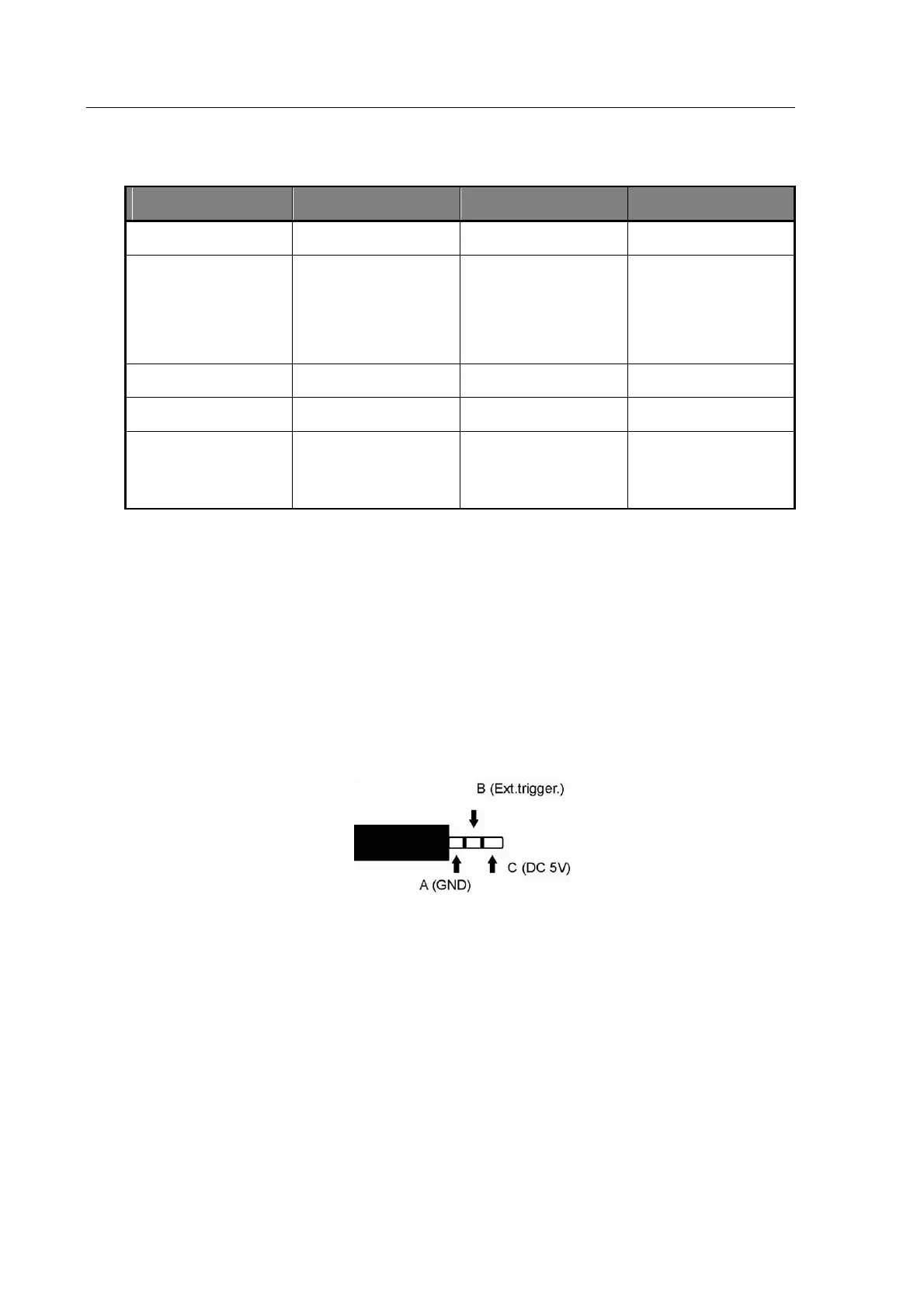
4.1.4.1 External Trigger (A-B)
The duplicates the action of the front panel trigger key. The input is TTL compatible and when
logic low is equivalent to operating the front panel trigger key. This input is level sensitive and
fully debounced, and includes a pull up resistor to enable shorted contacts such as relays or
footswitches to be used.
4.1.4.2 DC 5V Output (A-C)
Output DC 5V for user’s applications (max. current 1.5A)
Figure 4-2 the contact assignment of the phone jack
4.1.5 GPIB Connector
The General Purpose Interface Bus (GPIB) is a parallel port which allows communication
between the instrument and other devices such as PCs fitted with a suitable interface card. The
GPIB port allows remote control of the instrument for measurement of components and the
collection of measurement results. For details of GPIB control and commands see section 6.
Devices should be connected to the instrument using a standard GPIB 24-pin connector
assembly with a shielded cable. Use of the standard connector consisting of a plug and