- 11 -
4.2 Upper limit setting and zero trim:
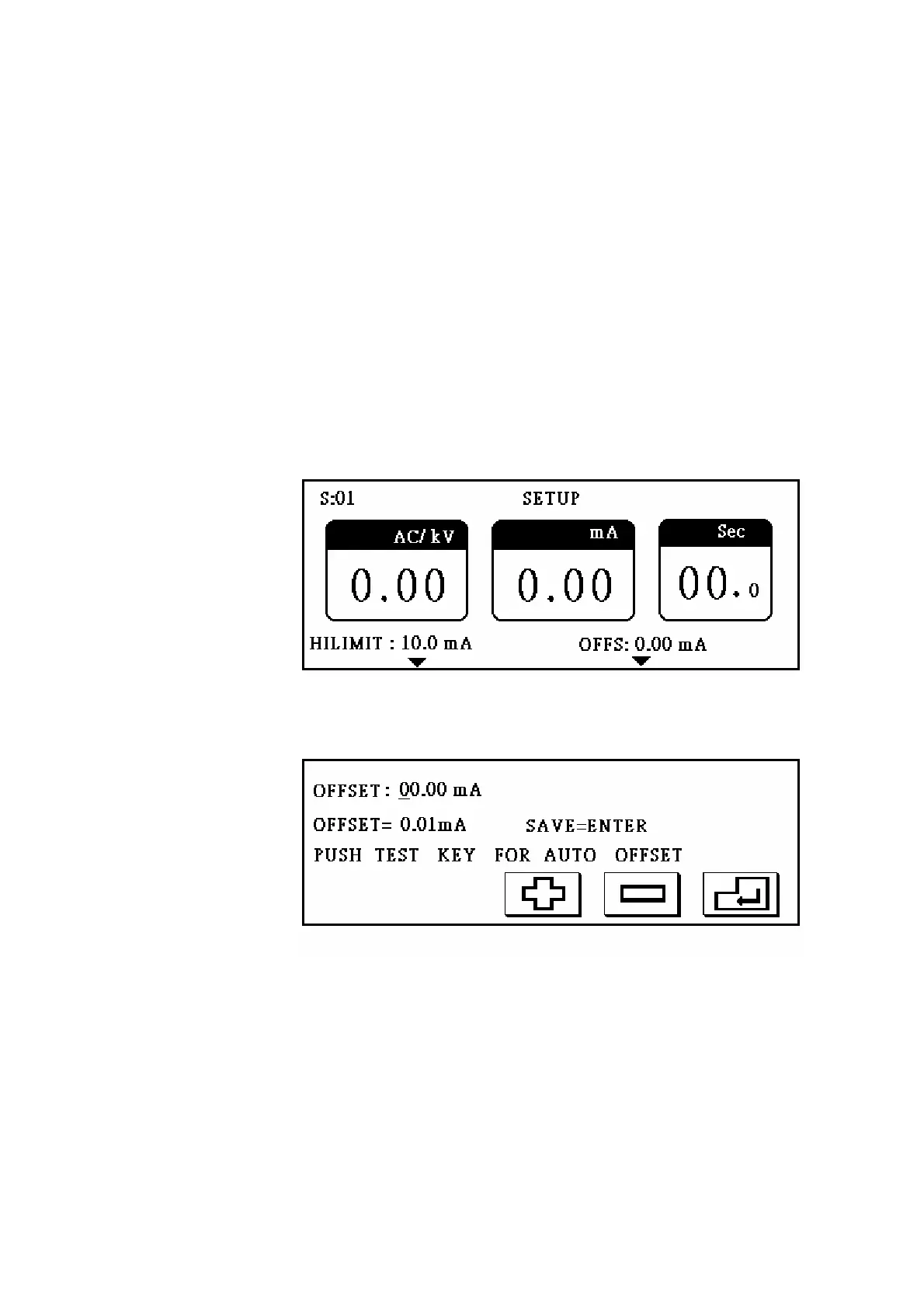
Press S2 to enter setting display as figure 3.
Parameter 1 is upper limit setting. Press S2 in setting display to enter upper limit
setting display. Upper limit setting procedure is the same as the voltage setting
procedure; if tested current is higher than upper limit, the display will show HILMIT
and FAIL light will turn on.
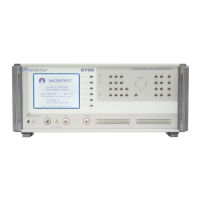
Parameter 2 is zero trim setting. Press S4 in setting display to enter zero setting
display as figure 4. There are two setting modes; one is manual setting, the other is
automatic setting. For manual setting, the procedure is the same as voltage setting.
For automatic setting, press TEST button and then the tester will execute testing by
the set voltage and display the tested result on the screen. After testing, screen will
show SAVE=ENTER. Press ENTER to save tested value, or press EXIT to quit
without saving.
Figure 3
Figure 4