- 17 -
6. REMOTE CONTROL:
There is a remote port (REMOTE) on the rear panel of the tester. To control the tester output
from external signals, please connect the cable to the connector. Because the control is from
exterior, please avoid operators contacting high voltage output terminal.
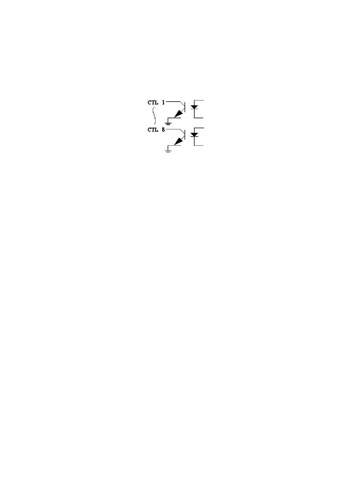
Circuit
PIN# NAME FUNC
1 CTL1 WIND1
2 CTL2 WIND2
3 CTL3 WIND3
4 CTL4 WIND4
5 CTL5 FIXTURE
6 CTL6 PASS
7 CTL7 FAIL
8 CTL8 H.V. ON
9 V1 +12V
10 SW1 TEST
11 SW2 ABORT
12 RST RESET
13 V2 +5V
14 V3 +12V
15 GND
Descriptions:
(1) TEST: A test is performed whenever GND (pin15) and SW1 (pin10) are shorted.
(2) ABORT: Test is abort whenever GND (pin15) and SW2 (pin11) are shorted.
(3) RESET: System is reset whenever GND (pin15) and RST (pin12) are shorted.
(4) PASS: To indicate the PASS state.
Active: Ground
Inactive: Floating
(5) FAIL: To indicate the FAIL state.
Active: Ground
Inactive: Floating