Do you have a question about the Microtest CT-8700 and is the answer not in the manual?
Lists included accessories and user manual.
Explains symbols and abbreviations used in the manual.
Provides essential operating procedures and conventions.
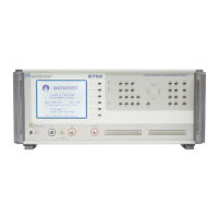
Overview of the tester's front panel layout and features.
Detailed description of the tester's front panel components.
Details the test points and their connections for measurements.
Describes the connectors and ports on the rear of the tester.
Explores the core functions and diagnostic capabilities of the tester.
Guides through the self-test routine for system diagnostics.
Displays instrument model, software version, and date.
Details the different measurement modes available on the tester.
Setup and operation for conductance measurements.
Setup and operation for RLC measurements.
Setup and operation for insulation resistance tests.
Setup and operation for withstand voltage tests.
Procedures for calibrating the tester for accuracy.
Calibrating for open and short circuit conditions.
Calibrating conductance measurement accuracy.
Calibrating DC High/Voltage measurements.
Calibrating AC High/Voltage measurements.
Calibrating insulation measurement accuracy.
Function to identify and locate specific pin connections.
Verifies the 4-wire connection integrity of the fixture.
Configuration settings for the tester's operation.
Configuring environmental settings like contrast and language.
Enables or disables the self-test on power-on.
Sets the power line frequency for the tester.
Controls the audible feedback for key presses.
Manages key protection and password settings.
Adjusts the brightness and contrast of the LCD display.
Toggles the LCD display between normal and inverse modes.
Selects the display language (Chinese or English).
Configures settings related to test execution.
Sets alarm behavior for test results (PASS/FAIL).
Controls the display of test data during or after a test.
Configures automatic printing of test reports.
Sets the internal clock and calendar of the tester.
Establishes a password for system security.
Configures the output port settings for data transfer.
Controls the printing of test data and reports.
Configures and performs Open/Short circuit tests.
Sets the threshold values for O/S detection.
Adjusts the speed of the O/S scanning process.
Configures detection of O/S ends during scans.
Defines the stop mode for intermittent tests.
Sets the timer for intermittent O/S tests.
Generates and displays statistical test results.
Defines test parameters, signals, and limits for sequences.
Configuration for Open/Short tests within sequences.
Configuration for Conductance tests within sequences.
Configuration for R/L/C tests within sequences.
Edits test modes and parameters for sequence routines.
Executes programmed sequence tests.
Runs sequences based on current setups.
Loads and runs previously saved sequence test files.
Manages test files, including loading, saving, and deletion.
Loads existing test files into memory.
Creates and saves new test files.
Removes test files from storage memory.
Organizes test files by various criteria.
Displays file records in a simplified view.
Pinout details for RS-232C cables.
Pinout details for printer cables.
Pinout and signal definitions for remote control.
| Brand | Microtest |
|---|---|
| Model | CT-8700 |
| Category | Test Equipment |
| Language | English |